
A welded cover plate on a bridge girder, a rail fastening clip, or a pavement layer may remain intact under loads well below its static strength, yet accumulate damage after millions of repetitions. This is material fatigue: local damage caused by fluctuating stress, usually beginning at a notch, defect, interface, or heavily stressed detail. Cracks can then grow until fracture or loss of function occurs if they are not detected in time.
Transport infrastructure is especially vulnerable because loads are repetitive, variable, and sustained over long service lives. Traffic, axle passages, braking, thermal restraint, wind-induced vibration, wheel-rail contact, and machinery vibration rarely produce one simple load case. Their effects depend on geometry, workmanship, corrosion, drainage, support conditions, and maintenance history. Effective fatigue management therefore relies on identifying critical details and realistic load spectra, not simply selecting a material with high nominal strength.
How fatigue damage develops
Fatigue is commonly described in three stages: crack initiation, crack propagation, and final failure. At the microscopic scale, repeated deformation can produce persistent slip bands and microcracks. In structural components, cracks may start at a weld toe, bolt hole, sharp re-entrant corner, corrosion pit, grinding mark, casting discontinuity, or material inclusion. Concrete behaves differently, but cyclic loading can still cause microcracking, bond deterioration, and gradual stiffness loss.
One difficulty is that visible deformation may remain limited until the damage is advanced. A member can appear serviceable while a crack grows beneath a connection plate, through a welded detail, inside an anchorage zone, or below a pavement surface. Final fracture can then occur quickly once the remaining intact section is no longer able to resist the applied load.
Stress range matters more than peak stress alone
For many metallic details, fatigue sensitivity is governed mainly by stress range: the difference between maximum and minimum stress in a cycle. Mean stress, residual stress, load sequence, and overload events also affect performance. A modest stress range repeated many times may cause significant damage, while occasional heavy vehicles can dominate fatigue demand at a detail already close to its fatigue threshold.
Design and assessment often use S–N data, relating stress range to the number of cycles to failure for a defined material and detail category. The detail category matters. Two steel members made from similar steel may have very different fatigue resistance if one has a smooth, well-finished transition and the other includes a transverse weld or geometric discontinuity. Nominal member stress alone is therefore not sufficient for judging fatigue performance.

Where fatigue appears across transport infrastructure
Steel bridges and ancillary components
On steel bridges, fatigue commonly concentrates at welded attachments, diaphragm connections, stiffener terminations, gusset plates, cross-frame details, orthotropic deck ribs, hanger connections, bearings, and expansion-joint components. Repeated wheel loads create stress cycles in primary girders as well as local distortion in secondary details. Out-of-plane bending and secondary stresses can be particularly significant because simplified global models may not capture them clearly.
Corrosion intensifies the problem by reducing section thickness and creating pits that can initiate cracks. Water retained at joints, failed coatings, leaking deck drainage, and debris accumulation can therefore increase fatigue risk indirectly. Hydraulic and foundation conditions also matter: scour or bearing movement may alter load paths and introduce unanticipated local actions.
Railway rails, welds, and fastenings
Rails are subjected to very high numbers of wheel passages. Contact fatigue may initiate at or near the rail head under repeated wheel-rail contact stresses, traction, braking, and steering forces in curves. Surface defects can develop into more serious internal cracking if inspection and suitable rail maintenance do not intervene early.
Rail welds, insulated joints, fastening systems, switch components, and bridge-track interfaces also require attention. Local stiffness changes can increase wheel loads, particularly where track geometry has deteriorated or support conditions vary. Ballast degradation, slab-track defects, poor drainage, and uneven subgrade response may therefore increase fatigue demand even when the steel or concrete component appears sound.
Pavements and concrete elements
In flexible pavements, repeated axle loads contribute to fatigue cracking in asphalt-bound layers. Tensile strains near the bottom of an asphalt layer are often important, while aging, temperature, moisture damage, and poor bonding between layers can accelerate deterioration. Cracks may begin at the bottom and propagate upward, although surface-initiated cracking can dominate under different material and environmental conditions.
Concrete bridge decks, rigid pavements, precast segments, and tunnel linings can accumulate fatigue-related damage through repeated flexure, shear, vibration, and restraint. Concrete does not usually fail in the same way as steel, but cyclic stress can increase cracking, reduce stiffness, weaken interfaces, and affect reinforcement bond. Reinforcing steel is also susceptible to fatigue, especially at bends, splices, welds, and locations where crack control is inadequate.
Loading spectra and dynamic amplification
Fatigue assessment requires a realistic representation of loading cycles rather than an assumed “average vehicle.” Traffic volume, axle configurations, lane distribution, growth projections, overload frequency, speed, road roughness, and operating restrictions all influence the load spectrum. For railways, relevant factors include axle load, train mix, speed, wheel condition, track geometry, and route characteristics.
Local stress ranges can exceed those calculated from static axle loads because of dynamic effects. Deck irregularities, expansion joints, rail defects, wheel flats, track transitions, and details prone to resonance can amplify structural response. The mechanisms behind these effects are addressed in our guide to dynamic loads in road infrastructure, including the role of vehicle interaction and surface condition in structural demand.
Variable-amplitude load histories are often reduced using cycle-counting methods such as rainflow counting and then assessed with a cumulative damage method. Miner’s rule is widely used as a practical approximation: each stress-range bin consumes a fraction of available fatigue life, and those fractions are added together. The method is useful, but it does not fully account for load sequence effects, residual-stress redistribution, crack closure, environmental degradation, or uncertainty in traffic and detail condition. Its results should be used as an input to engineering decisions, not as an automatic prediction of a failure date.
Factors that accelerate fatigue
- Stress concentrations: Abrupt thickness changes, cut-outs, holes, weld starts and stops, poor transitions, and misaligned connections concentrate cyclic stress.
- Welding quality and residual stress: Weld profile, undercut, lack of fusion, and residual tensile stress can reduce fatigue resistance at critical details.
- Corrosion and moisture: Pitting creates sharp local notches, while corrosion-fatigue processes can accelerate crack growth compared with dry conditions.
- Unexpected restraint or movement: Seized bearings, blocked expansion joints, settlement, thermal restraint, or track-structure interaction can introduce secondary stresses.
- Material aging and environmental exposure: Temperature cycling, freeze-thaw action, chloride ingress, ultraviolet aging of binders, and chemical exposure can alter material response.
- Construction tolerances and repairs: Eccentricity, distortion, poorly detailed retrofit plates, and unverified weld repairs can change stress flow.
Inspection: finding damage before it becomes critical
A fatigue inspection programme starts with an inventory of critical details. It should identify locations with high cyclic demand, known vulnerable geometries, difficult access, previous defects, water exposure, and limited redundancy. Inspection intervals should reflect consequence of failure, expected crack-growth rate, traffic exposure, environmental severity, and the reliability of the examination method.
| Method | Most useful for | Key limitation |
|---|---|---|
| Visual inspection | Surface cracking, corrosion, coating failure, distortion, leakage | Cannot reliably reveal concealed or very small cracks |
| Magnetic particle testing | Surface and near-surface flaws in ferromagnetic steel | Requires preparation and suitable access |
| Dye penetrant testing | Open-to-surface cracks in nonporous materials | Only detects surface-breaking discontinuities |
| Ultrasonic testing | Internal flaws and crack depth assessment in accessible steel sections | Interpretation depends on geometry, calibration, and operator skill |
| Strain and vibration monitoring | Response trends, abnormal dynamic behavior, model validation | Does not directly confirm every crack without targeted interpretation |
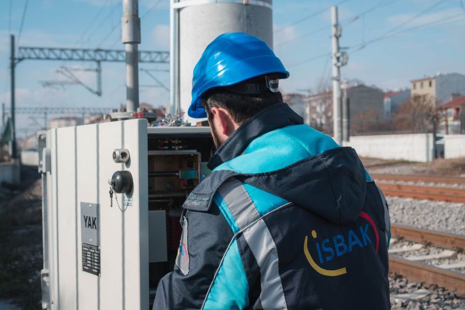
Cleaning and access are not minor practical issues. Rust scale, thick coatings, debris, moisture, and inaccessible geometry can conceal evidence or make nondestructive testing unreliable. Inspection records should identify the exact detail, the orientation and dimensions of each indication, the measurement method, environmental conditions, relevant traffic context, and repeatable reference points for later comparison.
From crack indication to engineering decision
Not every indication is an active fatigue crack, and not every crack has the same urgency. An engineering evaluation should determine whether a feature is a fabrication discontinuity, corrosion artifact, coating defect, or propagating crack; establish its location and dimensions; assess the stress range and load path; and consider fracture toughness, temperature, redundancy, and the consequences of local failure.
Crack-growth assessment can provide a more direct basis for action than a simple remaining-life calculation. Fracture-mechanics methods model crack growth from an initial crack size under anticipated stress cycles. The analysis requires defensible inputs for geometry, stress intensity, material properties, inspection detectability, and loading. Uncertainty can be substantial when the initial flaw size or actual traffic spectrum is poorly known, so conservative assumptions and follow-up inspections are often appropriate.
Interventions should remove the cause, not only the symptom
Possible measures include improving drainage, restoring bearing movement, reducing stress concentrations through detail modification, arresting or removing damaged material where justified, strengthening load paths, renewing protective systems, correcting track or pavement irregularities, and revising inspection intervals. Any drilling, welding, grinding, bolting, or heat-applied repair at a fatigue-sensitive detail requires a qualified repair design and procedure. A seemingly simple weld repair can introduce residual stress, defects, or unfavourable geometry if it is not engineered and inspected properly.
Monitoring can be useful after a repair or where access is difficult. Strain gauges, accelerometers, displacement sensors, acoustic methods, and periodic imaging may help identify changes in structural response. Their value depends on a defined decision framework: baseline measurements, trigger criteria, data-quality checks, and a clear process for engineering review. Continuous data collection without an interpretation plan rarely improves safety.
Designing for fatigue-resistant service
Fatigue performance is strongly influenced by early detailing decisions. Smooth load transfer, avoidance of abrupt section changes, appropriate weld placement and termination, accessible inspection zones, corrosion protection, drainage, and tolerance control can be more effective than simply adding material. Designers should also consider how maintenance teams will reach critical details and whether attachments, utilities, or future retrofit work could introduce new stress raisers.
For existing assets, the key task is to relate observed condition to actual operating demand. A bridge detail that has carried a known traffic spectrum without crack growth may require a different response from an identical-looking detail exposed to heavier traffic, severe corrosion, or unusual impact loading. Asset records, weigh-in-motion data where available, maintenance history, structural analysis, and repeated inspection observations are most valuable when considered together.
A practical inspection work order for a suspected crack in a welded detail should identify the exact weld and adjacent parent metal to be cleaned, the examination method required, the measurement datum, photographic orientation, and the access conditions that must be accepted before testing begins. At the next inspection, the same datum allows crack length and direction to be compared directly rather than estimated from photographs taken from different positions.

