

A road embankment may appear stable through several dry seasons, then lose stiffness quickly when prolonged recharge raises groundwater into its formation layers. This is more than a case of “wet ground.” Rising pore-water pressure reduces effective stress, changes seepage forces, and may mobilise fines. Hydrogeology helps transport engineers identify these mechanisms before they appear as rutting, slope deformation, track settlement, pavement pumping, or foundation distress.
For transport corridors, hydrogeology addresses the occurrence, movement, storage, and chemistry of groundwater, and its interaction with soil, rock, surface water, and built assets. It is closely tied to geotechnical design, while adding a time-dependent, catchment-scale view. A borehole records a water level on a particular day; a hydrogeological model examines why the level occurs, how it changes seasonally, where water enters and leaves the ground, and how excavation or drainage may alter the system.
Why groundwater is an engineering load case
Groundwater influences transport infrastructure through hydraulic conditions as well as material strength. In saturated granular soils, excessive local hydraulic gradients can transport particles. In fine-grained soils, changes in pore pressure may cause delayed consolidation settlement or reduce shear strength. In fractured rock, concentrated flow paths can supply tunnel inflows, soften weathered seams, or create local instability that widely spaced investigation points may not detect.
The relevant condition is seldom a single “design water table.” Engineers need to understand water pressures at depth, perched zones above low-permeability layers, artesian pressures beneath confining strata, and transient responses to rainfall, river levels, snowmelt, tidal effects, or pumping. Even a modest rise in groundwater can matter if it saturates a previously dry formation layer or reaches a weak interface within a cutting slope.

Effective stress and seepage
Soil and rock strength depend largely on effective stress: the share of total stress carried by the soil skeleton after pore-water pressure is taken into account. When pore pressure rises, effective stress falls even though the weight of the embankment, traffic, or structure has not changed. This explains why slopes can fail during wet periods after tolerating the same geometry for years.
Seepage direction is equally important. Downward seepage can increase stability in some circumstances, whereas upward flow may reduce effective stress and contribute to boiling, uplift, or internal erosion. Gradients can concentrate where permeable and low-permeability materials meet. Drain outlets, culvert interfaces, retaining structures, and excavation bases therefore need hydrogeological interpretation rather than generic assumptions about drainage.
Infrastructure decisions informed by hydrogeology
Route selection and corridor planning
Early hydrogeological screening can distinguish a manageable wet area from a corridor affected by persistent, high-risk groundwater conditions. Useful evidence includes geomorphology, drainage patterns, springs and wetlands, geological maps, nearby well records, aerial imagery, land use, and surface-water behaviour. Valleys, former channels, peat deposits, floodplains, and contacts between permeable and impermeable strata often warrant focused investigation.
The aim is not simply to avoid water. Some crossings cannot be avoided, and drainage can be engineered safely. Early work is valuable because it identifies uncertainty before alignment, profile, structure type, and construction sequence become difficult to change. It may also identify potential third-party effects, including drawdown affecting wells, wetlands, foundations, or groundwater-dependent ecosystems.
Road and railway earthworks
Subgrade moisture conditions affect bearing capacity, deformation, and vulnerability to seasonal damage. Hydrogeological investigations inform decisions on formation level, drainage strategy, earthwork material handling, and construction timing. They also help distinguish between local water sources: infiltration through surface defects, lateral hillside seepage, leaking utilities, an elevated groundwater body, or water held in a granular layer above clay. Each may require a different form of control.
On railways, groundwater can affect subgrade stiffness and promote fine-particle migration under repeated loading. In pavements, persistent saturation can weaken unbound layers and accelerate pumping or stripping in susceptible systems. Drainage features need a defined outfall and a flow path that can be maintained. A trench that intercepts water but cannot discharge it may simply move the problem elsewhere.
Bridges, retaining structures, and culverts
Bridge foundations require assessment of groundwater levels and pore pressures during construction and in service, particularly where excavations extend below the water table. Dewatering may alter conditions in adjacent ground, while seepage around abutments can contribute to erosion or loss of backfill. At water crossings, groundwater and surface-water processes overlap: changes in river level can reverse hydraulic gradients near foundations, and flood events can alter both scour exposure and bank seepage. The linked processes are examined in more detail in flood-resistant bridge design guidance on scour, hydraulics, and inspection.
Culverts and retaining walls can interrupt natural subsurface flow, causing water to accumulate behind a structure or emerge at an unprotected outlet. Backdrain performance, filter compatibility, outlet protection, and inspection access should be considered as parts of one hydraulic system rather than isolated details.
Tunnels and below-grade works
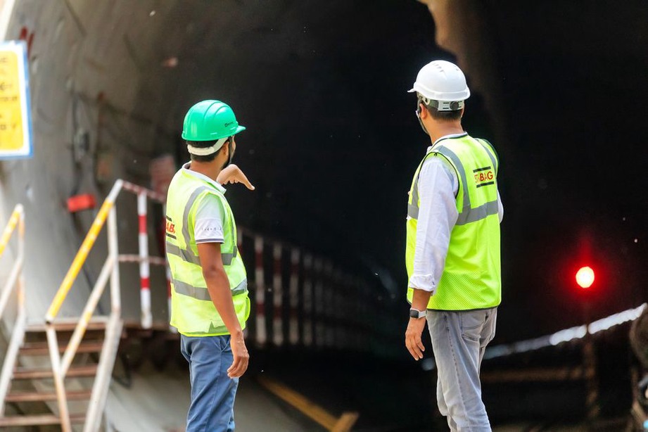
Tunnel excavation alters the groundwater system by creating a new low-pressure boundary. Inflows may be diffuse through permeable formations or concentrated along joints, faults, bedding planes, and karst features. The consequences can include face instability, piping, swelling or softening in susceptible materials, drawdown settlement at the surface, and effects on nearby water users or ecosystems.
Hydrogeological conceptual models inform the selection and verification of pre-construction measures such as probing, grouting, staged excavation, controlled drainage, or water-pressure management. Actual inflow and piezometric response during construction are particularly important. A departure from the predicted response may indicate an unidentified hydraulic connection.
Building a defensible hydrogeological model
A conceptual site model is the main outcome of the investigation. It is a tested explanation of the ground and water system, not merely a collection of logs, laboratory results, and water-level readings. The model should identify hydrostratigraphic units, permeable pathways, confining layers, recharge areas, discharge points, likely groundwater gradients, and links to surface water.
| Investigation element | What it can establish | Common limitation |
|---|---|---|
| Desk study and terrain review | Likely recharge, drainage, springs, former channels, regional geology | Cannot confirm conditions at construction depth |
| Boreholes and trial pits | Stratigraphy, weathering, seepage observations, sampling locations | Short-duration observations may miss seasonal highs |
| Piezometers | Water pressure at defined depths and responses over time | Poor installation or inappropriate screen intervals can mislead |
| Permeability and pumping tests | Hydraulic conductivity and aquifer response within tested conditions | Results may not represent fractures, heterogeneity, or larger scales |
| Water chemistry testing | Potential corrosion, scaling, contamination, and source tracing clues | Requires careful sampling and interpretation |
Nested piezometers are often needed where several water-bearing layers are present. A single standpipe can average conditions over its screened interval and conceal vertical gradients. Monitoring must also continue long enough to capture relevant variation. Seasonal wet periods, construction dewatering, and changes in nearby river levels may produce responses that a one-time visit will not reveal.
From investigation to risk controls
Hydrogeological findings should be translated into observable risks, trigger conditions, and verification activities. A practical register links each mechanism to available evidence, potential consequence, control measure, and monitoring method. Examples include:
- Elevated pore pressure in a cutting slope: monitor piezometric levels and movement; verify drainage continuity and outlet function.
- Internal erosion near a culvert: assess gradients, filter transitions, and signs of turbid discharge or void development.
- Settlement from tunnel-related drawdown: establish baseline water levels and surface deformation before excavation, then compare observed trends with predicted behaviour.
- Wet subgrade during earthworks: use moisture and groundwater observations to manage sequencing, temporary drainage, and acceptance testing.
Instrumentation is useful only when the response plan is defined in advance. Piezometer data without installation records, baseline readings, a rationale for thresholds, or assigned review responsibility often do not affect project decisions. Monitoring also requires protection from construction damage, survey checks where relevant, periodic maintenance, and review alongside rainfall, river levels, pumping records, and construction activity.
Climate variability means historical conditions provide an incomplete basis for prediction. More intense rainfall can increase recharge and perched-water occurrence. Extended dry periods may cause shrink–swell movement in susceptible soils, while changing flood patterns can alter groundwater gradients near rivers. These mechanisms sit alongside the broader issues addressed in guidance on climate impacts and adaptation strategies for rail infrastructure.
Construction-stage safeguards
Temporary works can create the most acute hydrogeological hazards because excavation, pumping, loading, and drainage conditions change quickly. Dewatering should be treated as an engineered intervention with defined objectives, permitted discharge arrangements, contingency measures, and monitoring of both the excavation and nearby assets. Uncontrolled pumping can cause settlement, draw contaminants towards the works, destabilise slopes, or reduce water availability beyond the project boundary.
Field observations should continually test the conceptual model. New springs on a cut face, unexpected inflow, sustained turbidity, water loss in nearby wells, or piezometer behaviour inconsistent with rainfall may indicate a different flow path or hydraulic unit. Record each observation with its location, timing, water condition, and concurrent works, then update the model before changing excavation depth, pumping rate, or drainage arrangements.
