Wind rarely acts on a transport structure as a single, steady horizontal force. It varies along the span, shifts with terrain and corridor geometry, and can excite vibration modes that remain insignificant under gravity loading. Bridge decks, sign gantries, noise barriers, station canopies, retaining-wall screens, and rail electrification supports may therefore be governed by peak response, fatigue accumulation, serviceability limits, or operational restrictions rather than member strength alone.
The engineering task is to define the site wind climate, convert it into appropriate pressure and force effects, and assess the response of the complete structural system. That assessment reaches beyond aerodynamics and member design. It includes structural dynamics, foundations, connections, construction stages, inspection access, and the consequences of temporary closure or loss of function.
Why wind is a system-level load
Wind pressure rises approximately with the square of wind speed. Local gusts therefore matter: a modest increase in velocity can produce a much larger increase in pressure. The load on a structure also depends on air density, exposed area, shape, orientation, shielding, elevation, and local terrain effects.
A simplified expression for mean pressure is often written as q = 0.5ρV², where ρ is air density and V is wind speed. Design assessments require more than this relationship. They use code-defined reference winds, exposure factors, gust treatment, pressure or force coefficients, directional effects, and load-combination rules appropriate to the jurisdiction and structure type. The responsible engineering team must select and verify these inputs; they cannot be inferred from a generic equation.
Wind is also spatially nonuniform. On a long bridge, gusts may reach different parts of the deck at different times. On a tall viaduct pier, wind speed increases with height and may be modified by adjacent slopes, water surfaces, buildings, portals, or cuttings. These actions pass through bearings, diaphragms, bracing, foundations, and soil. A local aerodynamic change can therefore alter demands well beyond the exposed component.
Transport structures most sensitive to wind
All exposed structures require wind assessment, but sensitivity varies greatly with geometry, stiffness, mass, and operational role.
Long-span bridges and slender decks
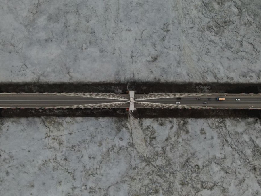
Suspension, cable-stayed, arch, and long continuous girder bridges can develop substantial lateral, vertical, and torsional response. Shallow decks with low torsional stiffness may be particularly susceptible to aerodynamic effects. Wind can cause turbulence-induced buffeting, vortex-induced vibration within certain velocity ranges, and, in adverse conditions, coupled aeroelastic instability such as flutter.
For these bridges, the issue is not simply whether the deck can resist static lateral force. Engineers need to assess modal properties, damping, deck and barrier geometry, cable response, aerodynamic derivatives where required, and wind conditions during service and erection. Sectional model testing, aeroelastic model testing, computational fluid dynamics, and full-scale monitoring can each provide useful evidence, although each method has different limits and uncertainties.
Railway bridges and overhead line equipment
Crosswinds affect both the bridge and railway operations. A bridge deck transfers wind effects to piers and bearings, while the train itself is subject to lateral aerodynamic loading. Their relative importance depends on vehicle form, bridge exposure, wind direction, line speed, embankment or viaduct geometry, and local turbulence.
Overhead contact systems introduce another source of sensitivity. Masts, cantilevers, wires, registration equipment, and connections require sufficient stiffness and clearance under wind-induced displacement. Excess movement can impair current collection or create maintenance problems even where individual members remain structurally sound. Wind assessment should therefore bring together bridge, track, electrification, and vehicle-interface disciplines.
Sign structures, lighting masts, screens, and canopies
These components often combine low mass with large exposed area. Connections and base details may be more critical than the visible primary member. A solid sign panel, acoustic screen, or canopy fascia can experience pressure differences across both faces, edge suction, and local peak pressures at corners. Repeated gust loading may initiate fatigue damage at welded attachments, bolted slip-critical interfaces, anchor rods, or bracket connections.
Open-area ratios also matter. Perforated screens and trussed structures do not behave like solid plates, while accumulated debris or later-added panels can alter aerodynamic performance. Asset records should document modifications that change projected area or flow paths.
Temporary works and construction stages
The least wind-resistant arrangement is often not the completed structure. Launching girders, free cantilevers, unfinished decks, form travelers, temporary towers, crane-supported elements, and partly installed noise barriers may have low stiffness, unrestrained edges, or unusual exposed shapes. Construction sequencing requires defined wind hold points, forecast thresholds, tie-down arrangements, and clear authority to stop work.
Key wind response mechanisms
| Mechanism | What drives it | Typical engineering concern |
|---|---|---|
| Quasi-static loading | Mean wind and slowly varying gust effects | Member forces, overturning, bearing and foundation reactions |
| Buffeting | Atmospheric turbulence acting on a flexible structure | Displacement, acceleration, fatigue, occupant or passenger comfort |
| Vortex-induced vibration | Alternating vortices near a resonant frequency | Repeated cyclic stress, cable vibration, local fatigue |
| Galloping | Unstable aerodynamic force on certain non-circular sections | Large-amplitude oscillation of cables, masts, or appendages |
| Flutter | Self-excited coupling between airflow and structural motion | Potential aeroelastic instability in slender bridge decks |
These mechanisms can occur at different wind speeds and directions. A structure with adequate static capacity may still need mitigation if vibration causes unacceptable acceleration, recurring fatigue cycles, or increased maintenance demand. Equally, visually dramatic cable movement may be operationally manageable if assessed stress ranges and clearances remain within acceptable limits. Diagnosis should rely on measured data and structural analysis rather than appearance alone.
From regional weather data to design actions
Regional wind records are a starting point, but transport corridors often pass through locations where conditions differ materially from those at the nearest meteorological station. Coastal headlands, valleys, ridgelines, bridge crossings, urban canyons, tunnel portals, and gaps between hills can accelerate or redirect flow. Terrain roughness and upstream fetch affect turbulence intensity; a long, smooth water fetch may produce conditions unlike those in a built-up inland setting.
A sound wind characterization normally considers:
- the governing return-period or reliability basis required by the applicable standard;
- reference wind speed definition, averaging period, height, and measurement exposure;
- terrain category, topographic speed-up, shielding, and changes expected over the asset life;
- wind directionality and seasonality, particularly where traffic or construction exposure is directional;
- local observations, project-specific measurements, or specialist studies for unusual sites;
- ice, rain, snow, vegetation, and attached equipment that may alter aerodynamic shape or mass.
Wind climate data are not interchangeable. A speed averaged over a short gust duration cannot be substituted directly for a longer-duration mean without the prescribed conversion framework. Wind-tunnel results are similarly valid only for the tested geometry, terrain representation, and assumptions about turbulence, boundary conditions, and structural properties.
Structural and geotechnical load paths
Wind-induced force must reach the ground through a continuous, ductile, and inspectable load path. For a bridge, that path may include deck diaphragms, bearings or restraints, pier caps, columns, foundations, and the surrounding soil or rock. An unintended gap, locked bearing, corroded connection, degraded anchor, or differential settlement can redistribute these actions.
Foundation performance requires close attention where wind produces large overturning moments. Uplift and compression beneath footings, lateral pile deflection, group interaction, cyclic soil degradation, and abutment movement can affect both strength and serviceability. Structures on soft ground may experience displacements that increase superstructure demands or compromise joints and rail alignment before nominal geotechnical capacity is reached.
This interaction is particularly important for tall signs, lighting towers, and noise barriers. Their foundations may be relatively small, yet wind can govern the design load. Field verification of concrete quality, reinforcement placement, anchor embedment, soil condition, and drainage is as important as checking the member above ground.
Serviceability, fatigue, and operations
Wind design is not limited to collapse prevention. Vertical and lateral deck movement affects expansion joints, bearings, drainage fittings, utility supports, and track geometry. Accelerations can affect pedestrian comfort on footbridges and staff safety on elevated maintenance routes. Repeated movement may loosen mechanical fasteners or wear cable-guide systems.
Fatigue assessment is important where turbulence produces large numbers of stress cycles. Details with abrupt geometric changes, weld terminations, corrosion pits, or variable clamping force are common initiation points. Inspection plans should focus on these details according to expected stress range, exposure, access, and the consequence of failure. The relationship between material selection, environmental exposure, and verification is addressed in Reliability Assessment of Composite Materials in Transport Infrastructure, particularly where lightweight components are being considered.
Operational wind management may involve speed restrictions, traffic controls, closure criteria, or work stoppages. Thresholds should come from a documented assessment of the asset and its operating conditions, rather than a generic regional wind-speed rule. The triggering measurement also needs to be defined: sensor height, exposure, averaging time, data-quality checks, communication route, and responsibility for decisions all determine whether a threshold has practical meaning.

Monitoring and inspection priorities
Permanent monitoring is most useful when it addresses a defined engineering question. An anemometer alone records wind at one point; paired measurements of acceleration, displacement, cable force, bearing movement, or strain can help establish relationships between wind events and structural response. Time synchronization is needed to relate gusts to measured behavior. Sensor placement should avoid wakes from parapets, towers, equipment cabinets, and nearby buildings that may distort the recorded flow.
Useful evidence after a severe wind event
- maximum and directional wind records, including data availability and sensor status;
- traffic restrictions, train movements, construction stage, and any observed abnormal behavior;
- condition of bearings, restraints, expansion joints, dampers, cable attachments, and anchorages;
- new looseness, fretting, paint damage, cracked sealants, displaced panels, or water ingress at interfaces;
- survey or monitoring comparison against established baselines where credible baseline data exist.
Inspections should separate wind damage from pre-existing deterioration. A displaced cladding panel, for example, may result from corrosion-reduced fastener capacity, insufficient installation torque, local edge suction, or a combination of these factors. Preserving evidence before repair—photographs, fastener remnants, position records, weather data, and material samples where appropriate—supports a defensible cause assessment.
Common weaknesses in wind-load assessment
Several recurring errors reduce reliability. One is applying a global force coefficient to a component with local discontinuities, deep edge members, equipment clusters, or altered porosity. Another is analysing the completed structure while overlooking erection stages. A third is considering peak wind strength without assessing dynamic response, damping uncertainty, or fatigue cycles.
Weaknesses also arise at interfaces. A bridge model may assume bearing behaviour that differs from field conditions; a sign design may omit future attachments; a rail assessment may use wind data measured below deck level; or a barrier replacement may increase solidity without checking posts and foundations. Change control is therefore part of wind resilience. Any modification that changes exposed area, profile, stiffness, mass, restraint, or drainage should prompt a proportionate engineering review.
For an existing asset, a useful first step is to prepare a wind-exposure register for each structure. Record the location and elevation, geometry, vulnerable appendages, load path, known dynamic behaviour, available weather data, operational consequences, and inspection access. Ranking the register by consequence and uncertainty helps identify where site measurements, detailed analysis, connection upgrades, or revised operating procedures are likely to reduce risk most effectively.