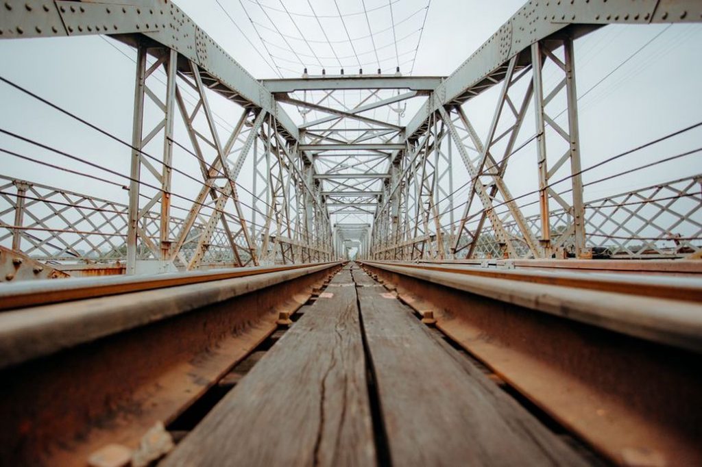
A steel railway girder may produce a different strain trace when a bearing starts to bind, even though its visible deflection looks unchanged. That is a diagnostic clue, not proof of damage: rail temperature, train speed, axle loading and sensor position can cause similar changes. The task is to separate those effects, identify a plausible fault and decide whether the evidence warrants a change in inspection or operation.
Railway bridges make this difficult. Loads arrive in moving axle sequences, sometimes with substantial effects from motion and vibration. Access beneath the track may be limited, and testing may have to fit between scheduled trains or into a short possession. An investigation is more useful when it starts with a question about a component or load path than with a general request for more data.
Start with the decision, then choose the measurement
Distinguish a condition observation from a structural assessment. Ultrasonic testing may establish that a weld contains a discontinuity; it does not, on its own, establish its growth rate or the connection’s remaining fatigue life. A measured deflection likewise describes response under particular loads and boundary conditions, not necessarily available capacity.
Before installing instruments, record the bridge configuration, drawings where reliable, inspection history, previous repairs, likely loading, restrictions and the uncertainty that matters most. Is a suspected crack longer than its visible trace? Does a bearing still permit longitudinal movement? Is a pier moving relative to the span? Each question calls for different evidence and a decision threshold suited to it.
| Diagnostic question | Useful evidence | Important limitation |
|---|---|---|
| Is a steel detail cracked? | Close visual examination with suitable surface or ultrasonic testing | Access, geometry and crack orientation govern detection |
| Has load distribution changed? | Strain and displacement under identifiable train passages | Train and environmental conditions must be comparable |
| Is a bearing restraining movement? | Relative movement, temperature and condition observations | A short record may miss seasonal behavior |
| Is hidden concrete deteriorated? | Targeted sounding, imaging and confirmatory opening or sampling | Indirect signals rarely identify a unique cause |
Instruments are no substitute for access. If debris conceals a bearing or a coating hides a suspected fatigue detail, cleaning and close inspection may resolve more uncertainty than months of remote measurements.
Investigate the load path and its critical details
Inspection coverage should follow wheel loads through the rail and track support, deck, primary members, bearings, substructure and ground. At each interface, look for signs that the assumed load path has changed: loose connections, local deformation, unintended restraint, differential settlement or deterioration that redistributes forces. This is more informative than applying the same test wherever access happens to be easy.
Steel connections and fatigue-prone regions
Repeated rail loads make weld toes, attachment ends, connection plates, riveted or bolted joints, and areas subject to secondary bending important inspection targets. A small crack can matter if it crosses a highly stressed section. Magnetic particle or dye penetrant testing can reveal accessible, surface-breaking defects when the material and surface preparation suit the method. Ultrasonic testing can examine internal regions, though results depend on geometry, probe access and the procedure used.
Map the detail before testing: member orientation, weld profile, fastener pattern, corrosion, previous repairs and any visible indication. Subsequent examinations should refer to the same physical locations. “No crack detected” means little without the method, inspected extent, surface condition and detection limits.
Concrete, masonry and composite components
On concrete decks and substructures, sounding and ground-penetrating radar may help map delamination, reinforcement position or changes within a deck. Ultrasonic or impact-based measurements can help investigate internal continuity. Moisture, congested reinforcement, overlays and variable material properties complicate interpretation; selected openings or samples may be needed to establish what an anomaly represents. Chloride or carbonation testing can investigate deterioration mechanisms, but its findings need to be read alongside observed condition and exposure.
For masonry arches, examine joint opening, displacement, spandrel condition, drainage and signs of fill movement. A local anomaly does not necessarily lie in the arch barrel. On composite spans, suspected debonding, shear-connection problems or differing responses between materials may call for both inspection and load-response measurements rather than a single scan.
Measure bridge behavior under trains
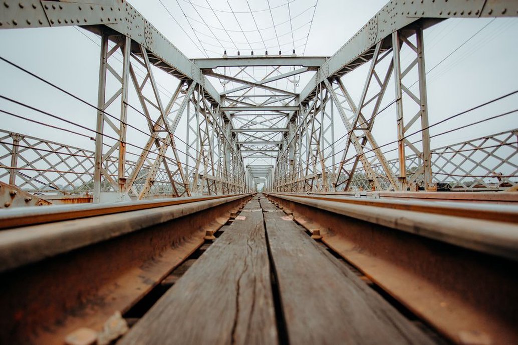
Instrumented train passages show how a bridge responds under traffic. Strain gauges record local deformation, displacement sensors track movement, accelerometers record vibration, and temperature sensors help explain slower changes. Document sensor orientation, attachment quality, sampling rate, synchronization and the train events selected for analysis. Without that context, a precise-looking trace may have little diagnostic value.
Train identification matters as much as instrument choice. Axle spacing and loading, speed, direction and track position all affect response. If individual axle loads are unavailable, passages should not be treated as equivalent tests. Comparing similar train classes and speeds, or using measured axle information where available, helps separate traffic changes from structural changes.
Deflection, strain and dynamic response
Deflection is most informative when measured relative to a stable reference and paired with load information. Strain readings at several positions can reveal a shift in load distribution between members, but each gauge samples the local field near its attachment. A gauge beside a stiffener or connection may capture behavior that does not represent the whole girder. Measurements at complementary locations make the interpretation more defensible.
Acceleration records can support estimates of vibration characteristics and flag unusual responses during train passages. A change in identified frequency is not a unique sign of cracking. Temperature, ballast and track condition, bearing restraint, added mass and train–bridge interaction may also affect it. Compare modal findings with inspection results, movement measurements and environmental records.
Static or controlled load tests can answer questions that ordinary traffic cannot, provided an assessed load case and safe operating arrangements guide the test. Agreement between measured and predicted response may increase confidence in a model. If they disagree, check the loads, instruments, assumed boundary conditions and model before drawing conclusions about capacity.
Use remote methods to locate, not certify
Photogrammetry and laser scanning can provide repeatable geometry for hard-to-reach trusses, arches and substructures. They help map distortion, compare member positions and document defects for later review. Drone imagery may improve coverage of exposed faces, subject to railway access, electrical and operational controls. An image alone cannot reliably expose a concealed fracture or establish material soundness.
Survey comparisons need stable reference points, consistent coordinate control and an estimate of measurement uncertainty. If an apparent displacement is about the same size as the registration error, it warrants a check; it does not verify structural movement. Close-range photographs should show scale and orientation so another inspector can find the detail.
Do not overlook bearings, foundations and the track interface
A bearing that no longer moves as intended can change stresses in an otherwise sound superstructure. Useful evidence includes movement across the bearing, rotation, temperature, corrosion, debris, damage to adjacent concrete and strain near the support. Seasonal movement and thermal gradients matter: a single reading on a cold morning cannot describe the full movement range. Where direct access is impossible, related measurements on the span and pier can help frame the question, but they offer less direct evidence.
Settlement, rotation, scour or erosion at a pier or abutment can change bridge geometry and boundary conditions. Select survey control points, underwater or near-water examinations where relevant, and ground or foundation investigations according to the suspected mechanism. Irregular track geometry near a bridge end may be an early operational clue, but the cause could lie in the approach embankment or track support. Compare bridge movement with approach behavior and maintenance records before assigning the cause.
Build monitoring around baselines and uncertainty
Continuous structural health monitoring makes sense when the question requires observations over time: a slowly changing crack indication, uncertain bearing movement, repeated excessive responses to moving trains or seasonal variation. The baseline should cover relevant train types and environmental conditions. A threshold based on a brief installation period might flag normal winter behavior or fail to reveal a defect hidden by routine variation.
Check data quality before analyzing trends. Look for sensor drift, missing samples, clock errors, changed attachments, electrical noise and readings outside plausible physical ranges. An alarm should distinguish a sensor fault from a possible structural change and preserve the underlying event data. Each threshold needs an associated response, such as remote verification, targeted inspection, a repeat measurement under controlled conditions or engineering assessment.
Analytical and finite-element models can test competing explanations. If added restraint at one bearing predicts the observed strain pattern and reduced girder stiffness does not, the result helps direct the next inspection. Calibration is not independent proof: different combinations of stiffness, load and boundary conditions can fit a small set of measurements. Reserve some observations for comparison, document parameter changes and report the plausible range of interpretations.
Turn an anomaly into an engineering decision
A defensible diagnostic record separates what was observed, what was inferred and what remains unverified. Retain sensor locations and calibration, test conditions, raw data, processing steps, inspection coverage and uncertainty. For a suspected fatigue crack, document the indication’s location and measured extent, the examination method’s limits, relevant stress evidence and the basis for recommendations on access, further testing or operation.
Escalation depends on consequence as well as confidence. An ambiguous signal at a critical connection may justify prompt close inspection; at a less consequential location, repeating the measurement may be the better first step. Equally, a clean scan should not override clear evidence of movement or distortion outside its coverage. Restrictions, repairs and reassessment require competent engineering judgment and coordination with railway operations, not an automatic dashboard rule.
Suppose a new strain peak appears at one support. Compare passages with recorded direction, speed and axle characteristics, check that day’s temperature, and verify the gauge attachment. If the peak persists under comparable conditions, inspect the bearing and nearby connection while the original event traces are still available to help locate the change.