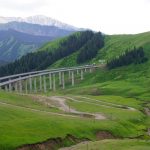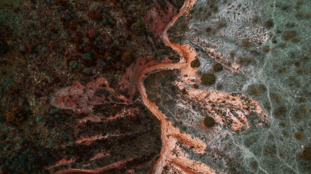
A shallow channel beside a road shoulder can do more damage than its depth suggests. Runoff concentrated along it may strip support from the pavement edge or carry fine soil out of the embankment. Filling the channel alone leaves the water source—and the failure mechanism—untouched.
Soil erosion is the detachment and transport of particles by flowing water, rainfall impact, waves or wind. For transport infrastructure, the distinction is between visible surface loss and erosion that changes an asset’s support or geometry. The latter can develop beneath pavement edges, at culvert outlets, along railway formation shoulders or around bridge foundations. Investigating it means tracing how water reaches erodible soil, where it gains energy and where the displaced material ends up.
Find the mechanism before treating the scar
Different mechanisms call for different investigations. Sheet erosion removes a thin layer across an exposed slope; rills and gullies develop where runoff converges. Flow from a culvert can scour the receiving channel or undermine a headwall. A shifting riverbank may erode toward an embankment or bridge approach. At a bridge, local scour around a pier or abutment differs from bed lowering across the channel. Fine particles can also escape through a poorly detailed drainage interface, causing settlement before much appears at the surface.
Site geometry matters as much as rainfall intensity. A modest flow collected along a long paved surface may discharge onto a small area of bare fill. Widespread staining on a slope, by contrast, may indicate slow surface wash rather than an immediate threat to its core. Record the upstream catchment, flow path, soil type, slope and outlet condition—not just the size of the scar.
Where damage becomes an operational risk
- Road edges and approaches: loss of shoulder or verge material can leave a pavement edge unsupported; erosion near a bridge approach may accompany differential settlement.
- Railway formations: washout of ballast or shoulder material reduces confinement and can change track geometry even while the rails remain continuous.
- Culverts and outfalls: scour can expose a pipe, undermine its bedding or headwall, or open a path for water around the structure.
- Bridge waterways: changes to the bed and banks can affect foundation exposure, approach embankments and inspection access.
- Cut and fill slopes: surface channels can expose less resistant layers or direct water into cracks. Erosion and deeper instability then need separate assessment.
Erosion is not the same as a landslide, though it can remove support at a slope toe or change infiltration enough to contribute to one. If movement extends beyond the eroded surface, the investigation needs to assess ground stability, not just the surface repair. That distinction is developed further in landslide risk mitigation for roads and railways.
Build an evidence trail from catchment to outlet
Start beyond the asset boundary. Drainage from adjacent land, changed land cover, temporary construction diversions and blocked crossings can all redirect flow onto transport earthworks. Compare current drainage paths with drawings where available, but do not assume the drawings reflect as-built conditions. Observations during or shortly after rain are especially useful: a dry-weather visit may miss overtopping, leakage or flow across a supposed drainage divide.
Use fixed photographic viewpoints and include scale references. Map the head and toe of each erosion feature, sediment deposits, exposed layers, ponding, outlets, cracking and deformation. Inspect a culvert’s inlet, barrel, joints, outlet and downstream channel as one system. For a railway, include ballast condition and track geometry records; for a road, note edge cracks, depressions and changes in shoulder width. A clear drain may still be causing damage where it discharges.
Where the consequences are high or the mechanism remains uncertain, targeted survey and subsurface investigation may be needed. Repeated cross-sections can reveal whether a gully or watercourse is enlarging. Bed-level surveys around bridges need comparable locations and a record of flow conditions. Sampling can distinguish coarse, freely draining fill from fine material vulnerable to particle migration. Instrumentation may track water levels or deformation, but its readings need to inform a defined decision about a plausible mechanism.
Set inspection priority by consequence and change
The deepest scar is not necessarily the most urgent. A small void beside an active track, exposed culvert bedding or erosion close to a foundation may warrant prompt engineering review. A larger surface rill on an isolated slope may allow planned treatment if its runoff source and rate of progression are understood. Compare conditions with earlier records, check for acceleration after storms and consider whether another event could remove the remaining support before the next inspection.
If support loss is suspected, manage the operational exposure while it is assessed. Measures may include restricting access to an affected shoulder, protecting a work area or applying railway or road operating controls through the responsible authority. A surface photograph cannot establish the extent of an underground void or the residual capacity of a foundation.
Match controls to water, soil and location
Erosion control needs to address concentrated flow as well as exposed soil. A surface cover may limit rainfall impact but cannot safely carry a concentrated discharge. An outlet lining may resist local scour without correcting leakage behind a headwall. Selection requires hydraulic, geotechnical and environmental review appropriate to the asset and the consequences of failure.
| Observed mechanism | Control principle | Verification focus |
|---|---|---|
| Diffuse wash on exposed earthwork | Protect the surface and establish stable cover | Continuity of cover, runoff concentration and establishment over time |
| Rills or gullies on a slope | Intercept or spread incoming flow and stabilize the channel | Upstream connections, channel transitions and downstream discharge |
| Scour at an outlet | Dissipate flow energy and protect vulnerable bed and banks | Edges, foundation of protection and effects farther downstream |
| Loss of fines within an earthwork | Control seepage and retain soil at drainage interfaces | Filter compatibility, joints and evidence of continuing settlement |
| Riverbed or bank erosion near a bridge | Assess hydraulic change and foundation exposure together | Bed trends, protection limits and post-event condition |
Vegetation and erosion-control blankets can work where surface-flow conditions suit them. Establishment time, shade, maintenance access and the prospect of concentrated runoff all affect that choice. Stone or other armoring needs assessment for hydraulic loading and possible loss of soil beneath it. A filter layer or suitably designed interface may be needed to keep fines from passing through gaps. Hard protection can also shift erosion to its edges or across the channel.
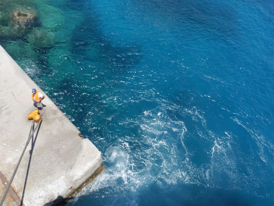
Construction-stage measures need the same scrutiny of flow paths. Stripped slopes and stockpiles can release sediment; a temporary diversion can send runoff onto an unprotected embankment. Capturing sediment reduces what leaves the site but does not replace keeping water off vulnerable soil. Inspect temporary controls after significant rain and whenever construction changes the drainage layout.
Repair the asset, then test the repair in service
Before reinstating an eroded shoulder or slope, establish the limits of loose or undermined material. Fill placed against an unsupported edge can hide a void and make it harder to detect later. Reinstatement may require excavation, suitable replacement material, controlled placement and restored drainage continuity; the details depend on the ground model and the asset. Exposed foundations or altered waterway geometry at a bridge or culvert require specialist assessment before protection is installed.
Completion checks should extend beyond the repaired patch. Confirm that inlets can accept flow, channels retain their intended grade, outlets discharge onto stable ground and transitions have not introduced weak points. Record as-built levels or cross-sections where future comparison matters. If vegetation forms part of the treatment, check its establishment and any bare gaps after installation.
Maintenance records should distinguish recurring sediment deposition from recurring soil loss. Sediment in a ditch may point to erosion upstream; repeated washout at the same outlet suggests the discharge or receiving channel remains unresolved. After a substantial storm, compare photographs from the same viewpoints and inspect both ends of the flow path. If a repaired culvert outlet holds while a new scour hole forms just beyond its protection, the erosion has moved rather than stopped.