A tunnel lining may look sound even while water migrates through joints, reinforcement loses section behind a repair, or local voids reduce contact with the surrounding ground. Durability assessment cannot therefore be reduced to a visual condition score. It is an evidence-based judgement of whether the lining, waterproofing and drainage arrangements, and the ground-lining system can continue to perform their required functions over a defined period.
In transport tunnels, those functions commonly include ground support, load transfer, water control, fire and operational safety, clearance retention, and protection of embedded components. The main risk is often an interaction rather than a single defect: leakage can introduce chlorides or sulfates; corrosion can lead to cracking and spalling; loss of section can then reduce structural capacity and increase sensitivity to ground movement.
Define durability in relation to the tunnel system
Durability is the ability to resist deterioration under expected environmental, mechanical, and operational actions while maintaining the required level of performance. A sound assessment separates condition, damage mechanism, and residual performance. A stained construction joint is a condition observation. A defective waterstop, failed drainage, or cracking caused by imposed deformation are possible mechanisms. Residual performance concerns whether observed and inferred deterioration affects structural resistance, serviceability, safety, or future maintainability.
This system view matters because lining types deteriorate differently:
- Cast-in-place reinforced concrete linings may be affected by cracking, leaching, reinforcement corrosion, chemical attack, and joint leakage.
- Precast segmental linings require particular attention to segment joints, gasket performance, bolt pockets, dowel zones, local edge damage, and differential ring distortion.
- Sprayed concrete primary linings can be susceptible to poor bond, debonding, cracking, water ingress, fiber corrosion where exposed, and degradation at interfaces with membranes or final linings.
- Masonry or older plain-concrete linings may suffer mortar loss, material weathering, voiding behind the lining, and localized instability where geometry or support conditions have changed.
Exposure classification must also reflect tunnel conditions. Marine aerosols at portals, de-icing salts carried in by road traffic, stray current near electrified railways, aggressive groundwater, exhaust deposits, and repeated wetting and drying can create sharply different exposure conditions along the same asset.
Build the assessment from records before field testing
A credible inspection campaign begins with an asset dossier. Original design drawings, geological baseline information, construction records, material certificates, waterproofing details, repair history, drainage maintenance logs, incident reports, and previous monitoring results help establish the intended function of the lining and identify likely vulnerabilities.
Construction-stage information is particularly useful. Records of overbreak, difficult ground, water inflows, grouting, ring-build tolerances, stoppages, damaged gaskets, concrete placement problems, and nonconformances can explain why an apparently isolated defect occurs at a particular chainage. Where records are incomplete, that uncertainty should be stated rather than replaced with assumed details.
Segment the tunnel into exposure and behavior zones
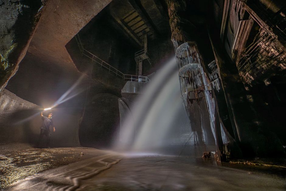
Treating an entire tunnel as a uniform structure can conceal important risks. Divide it into coherent zones based on lining type, construction period, geology, groundwater regime, cover depth, portal effects, cross passages, shafts, station interfaces, track or road environment, and observed defect patterns. A transition from drained to undrained construction, for example, may matter more than a nominally similar stretch of concrete several hundred metres away.
Each zone should have a defect map linked to chainage, elevation, circumferential position, photographs, and inspection dates. Repeatable location control helps distinguish actual deterioration from differences in observer judgement.
Inspect systematically: observe, measure, interpret
Visual inspection remains the starting point, but it requires a disciplined defect taxonomy. Record crack location, orientation, width where practical, length, branching, signs of displacement, moisture condition, deposits, rust staining, spalling, exposed reinforcement, surface softness, and any relationship to joints or penetrations. Classify water by its apparent source and behaviour: isolated dampness, active seepage, pressurized flow, joint-related leakage, or broad wet areas associated with drainage failure.
Crack pattern is often more informative than a single width measurement. Longitudinal cracking may indicate ring distortion, shrinkage, thermal restraint, or stress redistribution. Circumferential cracks near joints may reflect local bending, segment interaction, or construction effects. Diagonal cracking around openings can arise from stress concentration or displacement. No crack pattern alone proves its cause, but it should guide the next stage of investigation.
| Observation | Potential significance | Useful follow-up evidence |
|---|---|---|
| Persistent joint leakage | Waterproofing or drainage deficiency; possible transport of aggressive agents | Flow mapping, groundwater chemistry, gasket and drainage review |
| Rust staining and delamination | Possible reinforcement corrosion and bond loss | Cover survey, corrosion screening, targeted cores and steel exposure |
| Spalls at segment edges | Local impact, joint compression, installation damage, or distorted geometry | Ring geometry survey, joint-gap measurement, load-path review |
| Hollow response or localized distortion | Potential voids, debonding, or reduced ground contact | Impact testing, ground-penetrating radar where suitable, drilling verification |
| White deposits and material loss | Leaching or chemical interaction with water | Deposit and water analysis, concrete petrography if warranted |
Use testing to answer defined engineering questions
Non-destructive and minimally invasive methods are most useful when chosen to test a specific hypothesis rather than to produce large volumes of data. Rebound hammer measurements may identify relative surface variability, but they do not establish in-place strength on their own. Ultrasonic methods can support investigation of cracking, thickness variation, or internal anomalies, although results depend heavily on geometry, reinforcement, moisture, and coupling. Ground-penetrating radar may help locate reinforcement, identify interfaces, or indicate possible voids, but confirmation is often needed.
Targeted cores and drillholes can provide decisive evidence on lining thickness, carbonation depth, chloride content, sulfate-related alteration, compressive properties, porosity, and concealed interfaces. Because they are intrusive, sampling locations should follow a risk-based plan and be repaired appropriately afterwards. Petrographic examination can be especially valuable where chemical attack, freeze-thaw damage, alkali-related reactions, or poor consolidation is suspected.
Corrosion assessment should draw on several sources of evidence: cover depth, moisture exposure, carbonation or chloride profiles, visible symptoms, electrical screening methods where appropriate, and selective verification of bar condition. A single potential or resistivity reading does not directly predict section loss. Results must be interpreted in light of wetness, concrete composition, access conditions, and electrical continuity.
Assess water, ground movement, and load interaction
Water management is often central to lining durability. Blocked drains, damaged channels, failed waterproofing membranes, and altered groundwater flow can sustain saturation and hydrostatic pressure, mobilize fine materials, and distribute dissolved salts. Investigation should therefore extend beyond the lining surface to drainage outlets, sumps, inspection chambers, discharge trends, and water chemistry. A sudden change in water quantity or turbidity may warrant investigation of the surrounding ground as well as the lining.
Measured deformation provides context that visual inspection alone cannot supply. Convergence points, crack gauges, joint displacement sensors, settlement arrays, inclinometers, and survey targets can show whether movement is active, seasonal, or stable. Instrumentation works best when trigger values, reading frequency, checking procedures, and response actions are agreed before deployment. The wider role of ground observation is addressed in this blog’s guide to geo-monitoring for safer transport infrastructure.
From defects to residual life and intervention priority
Residual-life estimates should not be presented as a falsely precise single-number forecast. They are better expressed as scenarios based on exposure, observed deterioration rate, inspection confidence, loading, and planned maintenance. A stable non-structural crack in dry concrete may need periodic observation. A similar crack accompanied by accelerating leakage, corrosion evidence, and measured distortion requires more urgent investigation.
Prioritization should consider both likelihood and consequence. A small spall above a high-speed rail corridor, a lining defect beside critical electrical equipment, or deterioration near an emergency egress route may carry greater operational consequences than more extensive cosmetic damage in an accessible, low-consequence area. Restrictions, temporary protection, drainage cleaning, crack sealing, local repairs, grouting, corrosion mitigation, or structural strengthening should be selected only after the cause and load implications have been evaluated.
For significant findings, carry out an independent structural check using verified lining geometry, material condition, established reinforcement loss, groundwater assumptions, and plausible ground-lining interaction. This helps avoid repairing visible concrete while leaving deformation, water pressure, or poor ground contact unresolved.
Maintain an auditable condition record
A durable asset-management process records the evidence behind each decision: defect maps, raw test results, laboratory certificates, uncertainty limits, photographs, model assumptions, intervention rationale, and post-repair verification. Comparable condition records can also reveal recurring mechanisms across a network, such as portal chloride exposure or leakage associated with a particular joint configuration.
After repairs, establish a baseline immediately rather than waiting for the next routine inspection. For a repaired leaking joint, the baseline may include dated photographs, measured moisture condition, drainage-flow observations, crack or joint-gap readings, and a scheduled review after the next seasonal groundwater cycle. These repeatable observations can show whether the repair addressed the underlying mechanism rather than simply improving the lining’s appearance.