A bridge inspection starts well before the team reaches the deck or accesses the underside of a span. Previous reports, repair records, design drawings, traffic restrictions, flood history, and known defects indicate where attention is most needed. A crack recorded five years ago may be of limited concern if it has not changed. The same crack, if it has extended measurably or is accompanied by corrosion staining or local distortion, calls for closer assessment.
Inspection is not simply a search for isolated defects. It is a disciplined effort to identify deterioration mechanisms, establish their extent and rate, and determine whether they affect the load path, durability, serviceability, or public safety. Visual observations remain central, but access methods, nondestructive testing, measurement, and engineering interpretation are what turn those observations into defensible condition decisions.
Inspection objectives and levels
Inspection programmes usually combine several levels of work. Names and intervals vary by agency and jurisdiction, so owner requirements and applicable regulations must govern the process. The important distinction is the purpose and depth of each activity.
| Inspection activity | Primary purpose | Typical outputs |
|---|---|---|
| Routine visual inspection | Detect visible defects and changes across accessible components | Condition records, photographs, defect locations, maintenance actions |
| Detailed close-up inspection | Characterize a known or suspected defect at component level | Measurements, crack maps, corrosion extent, material test plan |
| Special inspection | Assess damage after collision, flood, fire, earthquake, overload, or other event | Safety decision, temporary restrictions, repair or monitoring scope |
| Underwater inspection | Examine submerged foundations and scour-sensitive zones | Foundation condition, bed-level observations, scour assessment evidence |
| In-depth investigation | Resolve uncertainty that visual inspection cannot answer | NDT results, samples, calculations, monitoring data, engineering evaluation |
A practical inspection plan identifies the decision that each task is intended to support. Ultrasonic testing, for example, may help define the depth of a steel flaw, while half-cell potential mapping can identify areas where reinforcement corrosion is more likely. Neither result, on its own, establishes remaining structural capacity. Test findings must be considered with geometry, loading, material condition, and the original structural system.
Preparation: turn records into an inspection hypothesis
Before fieldwork begins, engineers should review the bridge inventory, span arrangement, material types, bearing layout, drainage details, and any previous load rating or structural assessment. Drawings are especially useful for locating diaphragms, prestressing ducts, congested reinforcement, splice positions, and concealed fracture-critical details. If drawings are incomplete or unreliable, that uncertainty should be recorded in the inspection plan.
Previous observations should be compared, not simply copied into the next report. A useful pre-inspection defect register records the location, component identification, dimensions, photographs from the same viewpoint where possible, suspected mechanism, earlier recommended action, and evidence of progression. It helps direct attention to recurring leakage, seized bearings, failed joints, impact damage, and components exposed to de-icing salts or tidal spray.
- Define the required access: walking route, under-bridge unit, rope access, boat, drone, or temporary platform.
- Plan traffic management and fall protection before setting the inspection sequence.
- Identify confined-space, electrical, railway, waterway, and overhead hazards.
- Specify component numbering and photo-naming conventions so findings can be traced later.
- Calibrate measurement tools and provide a scale reference for close-up photographs.
- Set escalation criteria for findings that require immediate notification to the bridge owner.
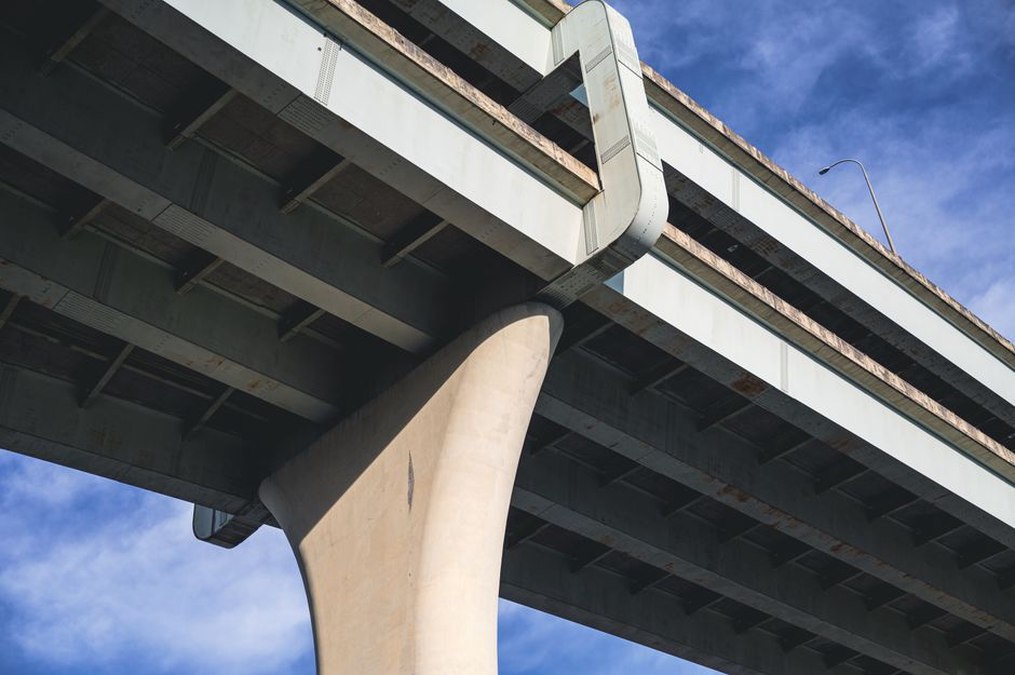
Systematic visual inspection
Visual inspection is most effective when it follows both the bridge load path and the water path. Inspectors commonly begin with the surrounding site and approaches, then examine the deck, joints, drainage, parapets, superstructure, bearings, substructure, foundations, and channel or ground conditions. This sequence helps connect symptoms that might otherwise seem unrelated. A blocked scupper, for example, can cause persistent joint leakage, accelerate bearing corrosion, stain a pier cap, and contribute to concrete deterioration at a support.
Deck, wearing surface, and drainage
Deck inspection considers crack patterns, spalling, exposed reinforcement, indications of delamination, patch condition, rutting or distress in the wearing surface, joint leakage, and ponding. Crack geometry matters. Random map cracking may indicate shrinkage, thermal effects, or surface deterioration. Longitudinal cracks may relate to reinforcement layout or deck behaviour, while localized cracking beside joints can accompany leakage and support deterioration. Interpretation depends on the deck construction and its restraint conditions.
Drainage should be examined as a functioning system, not as a series of isolated inlets. Check scuppers, downpipes, collector pipes, outlet locations, and splash zones. Water discharged onto concrete ledges, bearings, steel members, embankment slopes, or pier foundations can turn a manageable maintenance issue into widespread durability damage.
Concrete members
For concrete beams, slabs, piers, abutments, and caps, record cracking, spalls, delamination, efflorescence, rust staining, exposed steel, leaching, abrasion, impact damage, and construction defects. Where appropriate, measurements should include crack width, length, orientation, and position relative to supports, joints, tendons, and reinforcement. Hammer sounding or chain drag can identify areas likely to be delaminated, but these are screening methods rather than measurements of defect depth.
Prestressed concrete requires particular caution. Longitudinal cracking, unexpected deflection, local distress at anchorage zones, tendon exposure, or water entering ducts may warrant prompt specialist review. Drilling, coring, and other intrusive work near tendons should not proceed without reliable tendon-location information and an approved method.
Steel members and connections
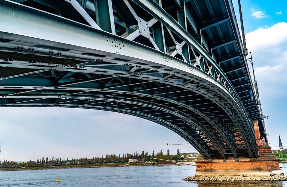
Steel inspection focuses on section loss, coating failure, corrosion products, deformation, fatigue cracking, loose or missing fasteners, damaged welds, and debris that retains moisture. Close visual access is particularly important at welded attachments, cope holes, web gaps, gusset plates, diaphragm connections, bearing stiffeners, and other geometric discontinuities. These details can experience high stress concentrations and are often difficult to inspect from the deck or roadside.
Corrosion assessment should distinguish surface coating deterioration from section loss that affects capacity or connection performance. Measure representative remaining thickness only where access, surface preparation, and the selected method support valid readings. One thickness reading cannot represent an entire corroded member, especially where pitting or crevice corrosion is present.
Access technologies and their limits
Inspection quality depends heavily on access. Binoculars or drone imagery can identify a suspect location, but they may not confirm a tight crack, failed seal, weld defect, or bearing condition. Under-bridge inspection units provide close access to soffits and outer girders, while rope access can reach complex or restricted locations. Boats and work platforms may be needed for piers in water. Each approach requires task-specific safety planning, particularly near live traffic, rail lines, navigable waterways, and energized equipment.
Unmanned aerial systems are useful at high elevations, in steep terrain, around inaccessible arches, and during rapid post-event reconnaissance. They can provide repeatable imagery, an overview of large surfaces, and reduced exposure during preliminary surveys. Their limitations include shadows beneath decks, inadequate pixel resolution, restricted viewing angles, wind, battery duration, and the inability to touch, sound, or directly measure many defects. To support comparison over time, images need adequate overlap, scale, controlled lighting, and location references.
Photogrammetry and laser scanning can produce geometric records of components and help identify deformation or material loss when survey control and data quality are adequate. They are useful where repeat measurement is needed. Surface texture, occlusion, moisture, and registration errors can, however, produce misleading results, so these tools should not be treated as automatic defect classifiers.
Nondestructive and minimally invasive techniques
Nondestructive testing should be selected to answer a defined question after visual review, rather than used as a substitute for engineering judgment. Material type, access, surface condition, reinforcement density, moisture, member geometry, and expected defect depth all affect method reliability.
| Technique | Useful applications | Key limitations |
|---|---|---|
| Impact echo or ultrasonic methods | Concrete delamination, voids, thickness variation, selected internal defects | Results depend on coupling, geometry, reinforcement, and signal interpretation |
| Ground-penetrating radar | Deck reinforcement mapping, moisture-related anomalies, potential delamination screening | Resolution is affected by moisture, conductivity, depth, and antenna frequency |
| Infrared thermography | Rapid screening for near-surface delamination under favorable thermal conditions | Requires suitable heating or cooling cycles and verification of anomalies |
| Half-cell potential and resistivity | Corrosion likelihood and moisture-related durability assessment in reinforced concrete | Does not directly measure reinforcement section loss or corrosion rate by itself |
| Ultrasonic thickness gauging | Steel thickness measurement and corrosion mapping | Needs accessible, prepared surfaces and representative sampling |
| Magnetic particle or dye penetrant testing | Surface and near-surface crack detection in accessible steel details | Surface preparation and trained interpretation are essential |
Verification is essential. An infrared anomaly can be checked through sounding, radar, or selective coring. A radar indication should be compared with drawings and local visual evidence. When cores are needed, their size, location, and reinstatement should be planned to avoid weakening critical sections, cutting reinforcement or tendons, and creating new routes for water and chlorides.
Bearings, joints, and movement behavior
Bearings and expansion joints warrant close attention because relatively minor maintenance failures can impose unintended restraint on the bridge. Inspect for accumulated debris, restricted movement, corrosion, cracked sole plates, damaged elastomer, displaced components, leaking joints, missing seals, and signs of contact where clearance should exist. If movement behaviour is uncertain, survey measurements, temperature records, and repeat observations may be more useful than a single visual judgment.
Misalignment or abnormal gap dimensions do not necessarily mean that a bearing has failed. Construction tolerances, seasonal temperature changes, creep, shrinkage, settlement, and previous repairs can all affect apparent position. Measured geometry should be compared with expected movement ranges, together with any distress observed in adjacent members.
Substructures, foundations, and site conditions
Bridge condition cannot be separated from ground and water processes. Inspect piers and abutments for cracking, rotation, settlement indicators, scour exposure, erosion, undermining, debris accumulation, seepage, slope movement, and damage caused by floating objects or vehicles. A shift in channel alignment or bank protection can alter flow concentration near a foundation even when the superstructure appears unchanged.
Underwater inspections may combine diver observation, tactile examination, sonar, bathymetric survey, and remotely operated equipment. Visibility, current, water depth, and bed material determine what can be observed directly. Bed-level surveys provide an important record, but they do not prove the condition of footings below the bed or the integrity of buried elements. Interpretation should account for the bridge's hydraulic setting, previous scour evidence, and foundation type.
For broader context on how inspection-friendly decisions affect long-term bridge performance, see innovative bridge design for durability, inspection, and resilience.
Recording, rating, and defect prioritization
A useful record allows another engineer to locate a defect, understand its significance, and determine whether it has changed. Each observation should identify the element, exact position, dimensions, orientation, severity, likely mechanism, inspection method, date, and supporting photographs. Photographs need both scale and context: one wide image to establish the location, one medium image to show the component, and one close image to document the defect.
Condition ratings are more useful when supported by narrative evidence. A numerical rating alone does not show whether deterioration is localized, active, load-sensitive, or caused by a correctable drainage fault. Prioritization should distinguish between:
- Immediate hazards, such as unstable concrete, severe collision damage, a potentially critical crack, or loss of support function.
- Defects requiring prompt engineering assessment, including active section loss, unexplained deformation, suspected scour, or prestressing-related distress.
- Planned maintenance items, such as coating renewal, joint sealing, drainage cleaning, or localized repairs before damage progresses.
- Conditions for observation, where the mechanism and baseline are known but available evidence does not yet justify intervention.
Urgency should reflect consequence as well as visible severity. A modest crack near a critical steel detail may require faster action than extensive superficial staining on a non-load-bearing surface. Equally, a defect that is not structurally critical may still need early intervention if it permits persistent water ingress into bearings, reinforcement zones, or foundations.
Monitoring when inspection snapshots are insufficient
Monitoring is appropriate when a condition may change between inspections or when the key question concerns behaviour rather than appearance. Crack gauges, displacement sensors, tiltmeters, strain gauges, accelerometers, corrosion sensors, and environmental measurements can be installed for defined purposes. The measurement plan should state the expected range, sampling frequency, alert thresholds, data-validation checks, and who is authorized to interpret alarms.
Sensor data need a baseline and context. Temperature-driven movement may be normal, while apparent displacement can result from sensor drift, loose mounting, or movement of the survey reference. Monitoring without provision for maintenance, verification, and regular data review can create false confidence. The broader methods and validation issues are addressed in advanced structural health diagnostics for transport infrastructure.
For a bridge with a recurring pier-cap crack, a focused follow-up may be more useful than installing a large number of sensors: place a crack gauge across the mapped fissure, record local air and member temperature, repeat photographs from fixed viewpoints, and inspect the nearby joint and drainage outlet after rainfall. This evidence can help distinguish stable thermal movement from progressive cracking associated with leakage, restraint, or support movement.