A tunnel face may look stable during excavation yet deform significantly hours later as stresses redistribute through the surrounding ground. This delayed response is one reason tunnel geotechnics cannot be reduced to a single ground classification or a standard support pattern. Each advance changes the stress field, groundwater flow paths, and the interaction between the ground, temporary support, and permanent lining.
Geotechnical uncertainty carries particular consequences underground. Pre-construction observations are limited, while conditions can change sharply over short distances. Competent rock may contain a weak fault core; dense sand may give way abruptly to running ground; and a localized water-bearing seam can alter excavation conditions. Investigation, design, construction, and monitoring should therefore treat the ground model as a working hypothesis that is tested continuously.
Why tunnels create difficult ground-engineering conditions
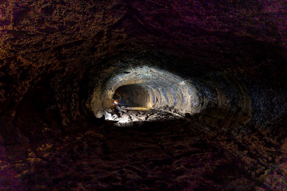
Excavation removes confinement around the tunnel perimeter. In rock, this can trigger joint movement, block falls, spalling, squeezing, or stress-induced fracturing. In soil, it may cause convergence toward the opening, loss of face stability, and settlement at the surface. The response depends on more than material strength: in-situ stress, discontinuities, groundwater pressure, tunnel geometry, excavation sequence, and the stiffness and timing of support installation all matter.
Scale is a central difficulty. Boreholes and geophysical surveys provide valuable evidence, but neither can identify every local discontinuity, boulder, void, or change in weathering. Construction teams need clear observational procedures: map each exposed face, compare findings with predicted conditions, record water inflows, and apply defined decision thresholds when excavation or support arrangements may need to change.
Building a ground model that is useful during construction
A desk study should bring together topography, geology, land-use history, records of previous excavations, groundwater data, utility information, aerial imagery, and information on nearby foundations or infrastructure. Historic mining, filled ground, karst features, buried channels, and former industrial works can be as important as mapped bedrock geology.
Field investigation develops design parameters and identifies hazards along the alignment. Depending on the project, it may include boreholes, core logging, in-situ testing, laboratory testing, geophysical methods, groundwater monitoring wells, and investigation adits. For rock tunnels, detailed core logging should record lithology, weathering, fracture frequency, joint orientation, aperture, infilling, roughness, and weak seams. For soil tunnels, key considerations include grain-size distribution, plasticity, density, permeability, shear strength, compressibility, and sensitivity.
From data collection to an observational baseline
The design ground model should distinguish between what is known, what remains uncertain, and which conditions require a response. Rather than relying on a single average parameter set, it should identify credible ranges and separate ground domains. A fault zone, for example, cannot be represented adequately by an average rock-quality value for the entire drive.
Baseline documentation also supports contractual clarity and risk control. It should describe anticipated ground and groundwater conditions in terms that can be checked during excavation. Construction observations can then be assessed against a stated expectation rather than informal judgement after conditions have already changed.
Major geotechnical hazards at the tunnel face
Face instability in soft ground
In shallow tunnels through granular soils, soft clays, silts, or mixed-face ground, insufficient face pressure can lead to ground loss. Possible consequences include localized voids, progressive settlement, damage to buried services, and deformation of adjacent foundations. Excessive support pressure also has consequences, including ground heave and disturbance above the tunnel.
For mechanized excavation, face support must be compatible with earth and water pressures, soil behavior, and the machine’s operating mode. In conventional excavation, staged methods, rapid closure of the support ring, forepoling, face reinforcement, or pre-support measures may be considered through project-specific engineering. The objective is to maintain face stability while limiting disturbance in the surrounding ground.
Faults, weak zones, and mixed ground
Faults and shear zones may contain crushed rock, clay gouge, high permeability, and highly variable strength. They can also direct groundwater toward the excavation. Where a tunnel crosses such a feature obliquely, conditions may vary across the face diameter, producing uneven loading and localized instability.
Mixed ground creates similar challenges where part of the face is in rock and part in soil, or where weathering has produced sharp contrasts in stiffness. Excavation tools, advance rates, support needs, and ground response may differ across the profile. Detailed face mapping and probe drilling ahead of the heading are particularly valuable in these areas.
Squeezing and swelling ground
Weak rocks and heavily fractured materials under high stress may continue to deform inward after excavation. This squeezing behavior can overload support, reduce clearance, and complicate permanent lining installation. It is influenced by the stress state, ground strength and deformation properties, groundwater conditions, and the confinement provided by the support system.
Some clay-rich rocks and soils swell after exposure to water or stress relief. Swelling pressure may develop over time, affecting invert stability and lining performance. Laboratory indices alone cannot define project behavior; mineralogy, moisture change, confinement, and excavation exposure time must be considered together.
Groundwater: pressure, inflow, and environmental constraints
Water is often the deciding factor in tunnel construction. It reduces effective stress in soils, softens susceptible materials, transports fines, increases face-pressure requirements, and can produce major inflows through fractures or permeable strata. In karstic limestone, water-bearing cavities and enlarged joints may create sudden inflow pathways that spaced boreholes cannot easily predict.
Groundwater control must address construction safety and off-site effects. Reducing pore pressures can cause consolidation settlement in compressible deposits, alter groundwater-dependent ecosystems, or affect nearby basements and wells. In urban work, drawdown assessment should therefore extend beyond the tunnel alignment.
Grouting, localized sealing, drainage, depressurization, or pressurized excavation may be suitable depending on the ground and environmental constraints. Their use should follow hydrogeological assessment rather than routine practice. Drainage remains important after construction as well, because uncontrolled water behind or beneath linings can cause uplift, leakage, frost-related damage at portals, and long-term deterioration. The principles addressed in Drainage Design for Reliable Transport Infrastructure are directly relevant to water collection, conveyance, inspection, and discharge around tunnel assets.
Settlement and interaction with the built environment
Surface settlement is often linked to volume loss around a tunnel, but its effects depend on more than the settlement trough. Differential movement, horizontal strain, building stiffness, foundation type, service connections, and the condition of buried utilities all affect damage susceptibility. A small movement may be significant where a brittle utility crosses a zone of differential strain, while a larger uniform movement may be tolerated by a flexible structure.
Predictions should define expected movement ranges and identify assets that need baseline surveys, protective measures, or closer monitoring. They should be updated when observed performance differs materially from predictions. Construction controls may include changes to excavation parameters, improved management of annular voids, revisions to the support sequence, or shorter advance increments. Any response should follow a defined engineering review process rather than an improvised correction after settlement has accelerated.
| Observed condition | Potential mechanism | Typical engineering response |
|---|---|---|
| Increasing convergence after support installation | Squeezing ground, delayed stress redistribution, inadequate ring closure | Review support timing, ground parameters, excavation sequence, and monitoring frequency |
| Turbid water inflow with fines | Internal erosion or ground loss pathway | Stabilize excavation, investigate source, reassess water-control measures |
| Localized surface settlement | Volume loss, void formation, utility leakage, inadequate face control | Verify survey data, inspect affected assets, investigate the tunnel-ground relationship |
| Rock falls or fresh cracking at the crown | Unfavorable discontinuities, overbreak, stress-induced damage | Map discontinuities, secure the area, reassess temporary support and excavation method |
Temporary support and the importance of construction sequence
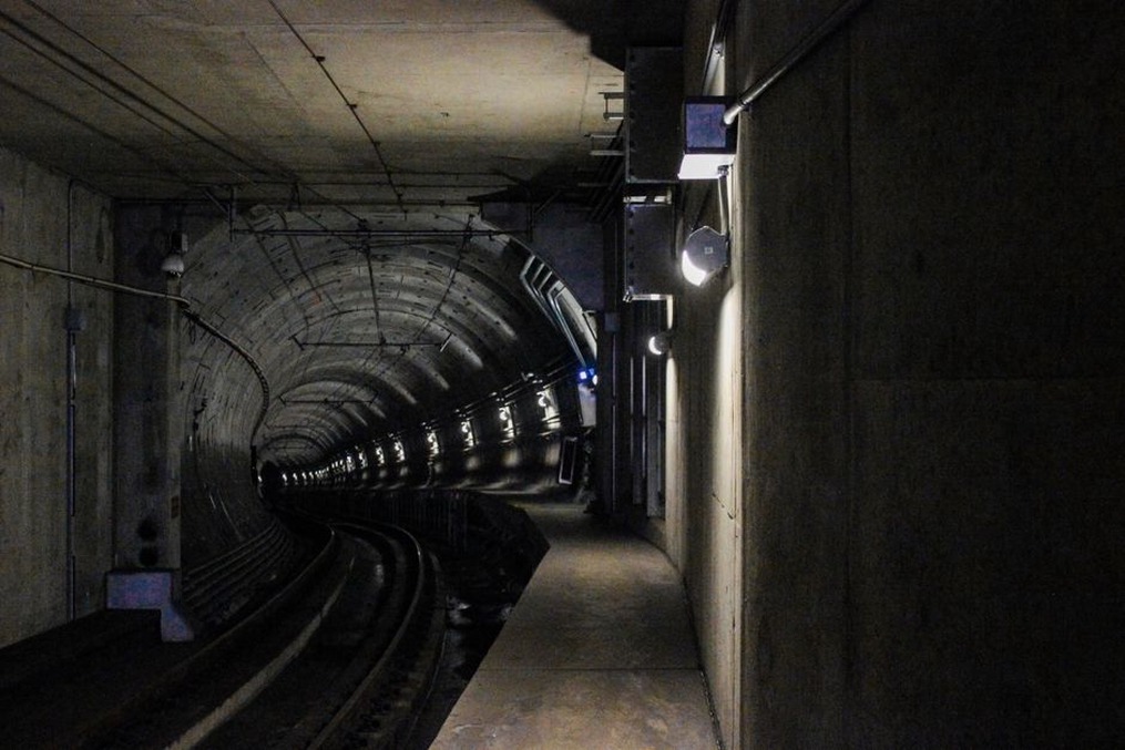
Temporary support becomes part of the structural system as soon as it is installed. Shotcrete, bolts, lattice girders, steel sets, spiles, and the initial lining interact with the ground. Their performance depends on contact quality, installation timing, continuity, and closure of the support ring. A technically suitable support installed too late may perform poorly because excessive deformation has already occurred.
Excavation sequence is equally significant. Full-face excavation, top-heading and bench arrangements, side drifts, sequential enlargement, and staged invert construction produce different stress paths. The selected sequence must reflect expected ground behavior, cross-sectional size, available stand-up time, water conditions, and limits on surface movement. Production-driven changes should be assessed for geotechnical consequences rather than treated as operational decisions alone.
Monitoring as a control system, not a reporting exercise
Instrumentation provides evidence of actual ground behavior. Common systems include convergence points, extensometers, settlement arrays, inclinometers, piezometers, load cells, strain gauges, pressure cells, and automated surveying. Instrument selection should follow the failure mechanisms that matter on the project. A piezometer is useful where pore pressure is a critical uncertainty, but it cannot replace convergence monitoring where lining closure is the main concern.
Monitoring plans need baseline readings, measurement frequencies that reflect construction activity, data-validation procedures, alert thresholds, communication routes, and defined actions. Thresholds are often organized as attention, alert, and intervention levels. Their values must be project-specific and linked to predicted performance, measurement uncertainty, and the vulnerability of nearby assets.
Interpreting trends rather than isolated readings
A single reading outside the expected range may reflect survey error, instrument damage, or a genuine ground response. Trend analysis helps separate these possibilities. Accelerating convergence, rising piezometric levels, or settlement that continues after excavation has moved away may indicate that the assumed mechanism needs review. Measurements gain engineering meaning when they are correlated with chainage, excavation stage, support installation, groundwater events, and face mapping.
Digital systems can improve access to data, but automation does not replace competent interpretation. The broader role of sensors, control logic, and validation in underground works is addressed in Tunnel Safety Technology: Detection, Control, Monitoring and Validation.
Portals, shafts, and transitions
Portal zones often combine shallow cover, weathered rock or residual soils, cut slopes, concentrated drainage, and weather exposure. The transition from open cut to tunnel can produce differential stiffness and settlement behavior. Slope stability, rockfall, erosion, and seepage need assessment alongside the tunnel excavation itself.
Shafts present different risks because they may intersect several aquifers and strata over a short vertical distance. Excavation support must limit lateral ground movement and water ingress while allowing safe construction of the base connection. Interfaces between shafts, mined tunnels, and bored tunnels require explicit analysis because geometry changes and stiffness discontinuities can concentrate load.
Managing uncertainty through observational construction
An observational approach works only when it is established before excavation begins. It requires plausible predicted behaviors, reliable monitoring, clear limits for acceptable performance, and contingency measures that can be implemented quickly. It is not a basis for starting work with an incomplete understanding of ground conditions and addressing problems later.
When a drive approaches a suspected fault, a practical pre-excavation hold point may require updated probe drilling, review of face mapping from the preceding advance, confirmation of groundwater trends, and approval of the support arrangement before the heading enters the zone. Recording the actual thickness, water condition, deformation response, and installed support improves the ground model for the next critical reach.