A dense-looking layer on a seismic section could be competent rock. It could also reflect a change in moisture or material composition. Beneath a road embankment or railway formation, the distinction affects where boreholes go and how investigators assess settlement risk. Surveying methods can fill gaps between intrusive tests, but a convincing ground model rests on several independent observations, not a subsurface image alone.
Start with the decision, not the instrument
A proposed bridge pier calls for different evidence than a recurring track geometry defect. The pier investigation may need the depth and variability of bearing strata; the track investigation may need to locate wet, deformable zones along an existing formation. Before choosing equipment, investigators should define the target depth, the smallest feature of concern, the property to be estimated and the uncertainty the project can tolerate.
It also matters whether the work is an investigation or monitoring. A one-time survey maps present conditions. Repeated observations can show change if acquisition geometry and processing remain comparable. Neither, on its own, establishes why ground is moving. Rainfall, drainage alterations, construction activity and seasonal effects may all warrant checking.
Faster measurements at and below the surface
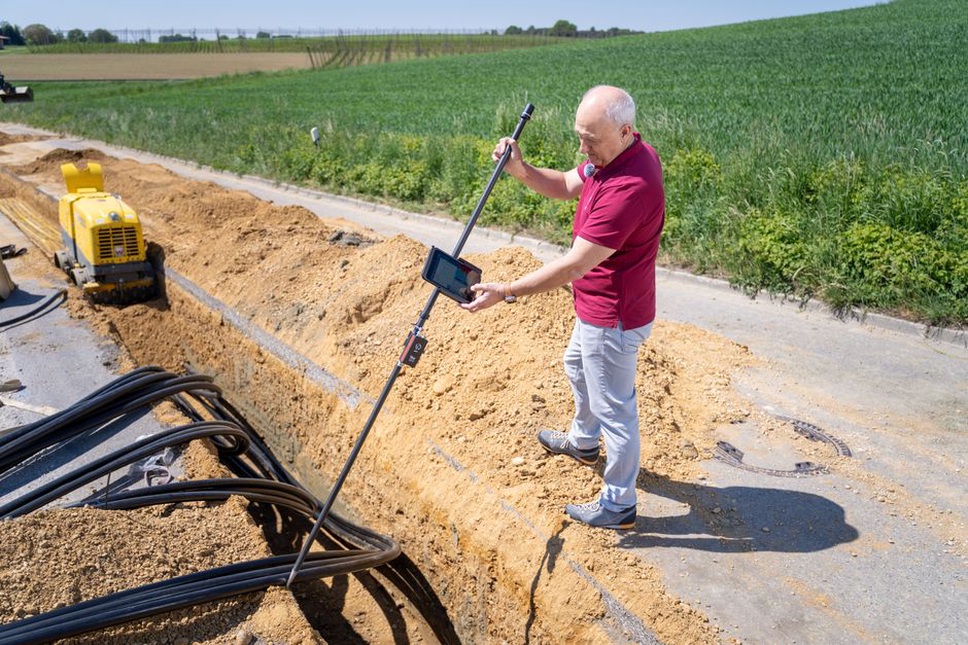
Instrumented probing and digital field records
Cone penetration testing produces a continuous depth profile of tip resistance and sleeve friction; a piezocone also measures pore pressure. Compared with widely spaced samples, the profile can reveal thin changes relevant to settlement or liquefaction screening. Interpretation still depends on soil type, drainage conditions and calibration against boreholes and laboratory tests. Gravel, obstructions and very dense ground can stop penetration.
Digital logging addresses a less visible part of surveying: keeping depth references, sampling times, instrument calibrations and field observations together. Georeferenced logs help investigators compare a probe with a nearby geophysical line without treating two separate locations as identical. Refusal, disturbed samples and missing readings belong in the record too.
Geophysics for the space between boreholes
Electrical resistivity tomography estimates how electrical resistance varies underground. It can locate contrasts associated with moisture, clay-rich material, bedrock or buried features, but the same resistivity value may have several explanations. Electrode contact, utilities and surface conditions can also affect results. Seismic methods offer another view: surface-wave surveys estimate shear-wave velocity profiles, while refraction methods can help map velocity contrasts. Velocity informs assessments of stiffness-related behavior; it does not directly measure foundation capacity.
Ground-penetrating radar can resolve shallow interfaces at relatively fine scale where conditions permit. Conductive clay or saline water may sharply limit its penetration. For transport assets, radar may be better suited to investigating a near-surface layer or void than defining a deep foundation stratum. Investigators might use it to flag a shallow anomaly, resistivity to examine the anomaly’s lateral extent and targeted drilling to establish what is present.
Remote sensing changes where field teams look
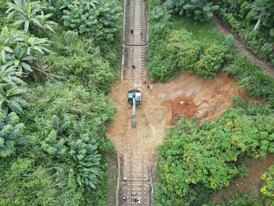
Airborne lidar records detailed surface geometry, including slope breaks, drainage routes and subtle ground-deformation features that a corridor inspection might miss. Drone photogrammetry can document exposed cuttings and earthworks over time, although vegetation and poor surface texture can degrade reconstructed ground surfaces. Neither method sees through soil. Both can help identify where subsurface testing would be useful.
Satellite interferometric radar, or InSAR, compares radar observations from different times to estimate movement along the sensor’s line of sight. It can reveal persistent displacement patterns across large areas, but vegetation, changing surfaces, viewing geometry and the availability of stable radar targets affect coverage. A measured signal does not identify the moving layer or prove that an embankment is failing. For a closer account of these methods in asset inspection, see [remote sensing for transport infrastructure diagnostics].
Along a long rail corridor, terrain and displacement data can help prioritize segments for ground surveys. They narrow the search; they do not verify that every unmeasured segment is stable.
Permanent sensors make the survey time-dependent
Distributed fiber-optic sensing collects measurements along a cable rather than only at isolated points. Depending on the system and installation, it may track strain or temperature along an embankment, tunnel approach or retaining structure. Temperature changes, cable coupling and installation damage can complicate the response. To investigate a suspected mechanism, compare fiber readings with appropriate independent measurements, such as survey markers, inclinometers, pore-pressure instruments or rainfall records.
Wireless transmission and automated dashboards make frequent readings easier to review, but frequent sampling does not guarantee useful spatial resolution. A sensor outside the deforming zone may precisely record the wrong location. Baseline readings taken before nearby construction or seasonal water-level change also make later departures easier to interpret.
Turning dense data into defensible ground models
Three-dimensional ground models can bring together borehole logs, probe profiles, geophysics and terrain data. Uncertainty should remain visible. Layer boundaries drawn between investigation points are estimates, and an anomaly without ground truth should be labelled as such. Machine-learning classification may help sort large datasets or flag patterns for review, but training data from different geology or acquisition methods may not transfer reliably.
Before acting on a digital survey, check:
- Location: Are sensor coordinates, elevations and depth datums consistent?
- Resolution: Could the method detect a feature at the depth and size of concern?
- Ground truth: Which interpretations are supported by samples or direct measurements?
- Repeatability: Have changes in instrument setup or processing been separated from real ground movement?
- Decision relevance: Would resolving the remaining uncertainty change the next investigation or maintenance action?
Suppose a resistivity section beneath a road approach shows a conductive zone near a settlement location. That is not enough to call it a leaking drain. Compare the anomaly with drainage records and the timing of settlement, then position a targeted probe or borehole to distinguish wet fill from clay-rich natural ground. Record its position against the geophysical line so the result can update the interpretation.