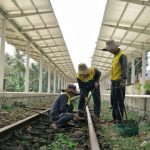
A rail defect rarely begins as an operational emergency. It may first appear as a subtle change in axlebox acceleration, a persistent variation in track geometry, an unusual strain cycle at a turnout, or a localized temperature pattern in the ballast. The value of modern monitoring lies in detecting these weak signals early enough to verify their cause and plan intervention before speed restrictions, component failure, or derailment risk develops.
Rail track monitoring now extends beyond periodic geometry surveys and visual patrols. Those methods remain essential, but they are increasingly supported by onboard measurement, fixed sensors, machine vision, distributed fiber-optic systems, automated inspection vehicles, and data platforms that connect observations with maintenance decisions. The objective is not simply to gather more data. It is to create a traceable link between measured condition, uncertainty, defect mechanism, risk, and an appropriate maintenance response.
From discrete inspections to condition evidence
Traditional track inspection relies on defined intervals, trained observation, and targeted measurements. It can identify many visible defects effectively, including damaged fastenings, rail surface damage, drainage blockage, vegetation intrusion, and geometry exceedances. Its main limitation is temporal and spatial coverage: defects can develop between inspections, while inaccessible or heavily used locations may be difficult to inspect frequently.
Continuous and semi-continuous monitoring changes the available evidence. Instead of treating a track section as acceptable until its next inspection, engineers can assess trends: whether alignment deterioration is accelerating, whether repeated wheel impacts occur at the same location, or whether a wet formation produces recurring stiffness changes after rainfall. This matters because an individual measurement can be affected by train speed, temperature, axle load, sensor coupling, or processing settings. A consistent trend supported by several sources is usually more informative.
Monitoring does not replace inspection; it directs it more effectively. Field verification is still needed to distinguish, for example, a genuine void beneath a sleeper from a signal caused by a passing vehicle’s response, or a rail-surface indication from a vision-system artifact caused by glare.
Mobile measurement systems: frequent coverage at network scale
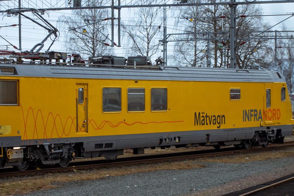
Track-recording cars remain a primary source of network-wide condition data. Modern systems combine inertial measurement units, optical sensors, laser profilers, cameras, global navigation satellite system positioning, and sometimes ground-penetrating radar. They measure gauge, crosslevel, longitudinal level, alignment, twist, curvature, rail profile, and selected features of the track environment.
The main advance often comes from sensor integration and repeatability rather than a single instrument. A geometry deviation is more useful when it can be located accurately, compared with several earlier runs, related to local speed and loading conditions, and reviewed alongside images of ballast, drainage, and rail condition. Reliable positional referencing is therefore a central technical requirement. Satellite positioning may degrade in tunnels, urban canyons, cuttings, or densely wooded corridors. Inertial navigation, track maps, balises, odometry, and fixed reference features may be needed to maintain location accuracy.
Vehicle-response monitoring from service trains
Dedicated inspection vehicles provide high-quality measurements, but they cannot always survey every route frequently. Sensors installed on in-service vehicles can supplement these surveys. Accelerometers fitted to axleboxes, bogies, car bodies, or suspension components record the vehicle response to the track. Algorithms then identify recurring, location-specific signatures associated with faults such as dipped joints, corrugation, rail defects, localized geometry irregularities, hanging sleepers, or poor support conditions.
This is often called indirect track monitoring because the sensor records vehicle dynamics rather than track geometry directly. Its practical advantage is coverage: repeated passages by passenger or freight trains can build a detailed history of track response. Interpretation remains difficult. Signals vary with vehicle type, suspension condition, train speed, wheel condition, load, and route characteristics. Models should account for these variables, and alerts should be calibrated against confirmed field findings rather than treated as defect diagnoses by default.
Machine vision for visible asset condition
High-resolution line-scan cameras and structured lighting increasingly support automated visual inspection of rails, sleepers, fastenings, ballast shoulders, crossings, and overhead or wayside assets. Computer vision can identify missing clips, damaged pads, sleeper cracks, ballast fouling indicators, vegetation encroachment, loose components, and rail-head surface features. Thermal cameras can provide further evidence where abnormal heat is relevant, such as possible friction effects or electrical component anomalies.
For rail-surface inspection, imaging must suit the defect type. Conventional images cannot reliably identify some cracks and internal flaws because the critical discontinuity may lie below the surface or be too fine to detect under variable lighting. Vision is most useful for repeatable visible classification and change detection. Ultrasonic, eddy-current, or other nondestructive evaluation methods are needed for subsurface or near-surface rail integrity.
Artificial intelligence can speed up image review, particularly on large networks where manual examination of every frame is impractical. Classification performance alone is not enough for engineering use. A useful system must document:
- the defect classes it can and cannot identify;
- the lighting, contamination, speed, and weather conditions represented in validation data;
- false-positive and false-negative behaviour at operational decision thresholds;
- how image findings are linked to an asset location and inspection record; and
- the required human review and escalation process.
A model trained mainly on clean, dry track imagery may perform poorly in snow, standing water, heavy contamination, or low-angle sunlight. Revalidation is necessary when cameras, illumination, track components, operating practices, or the data population change.
Fixed sensors at high-consequence locations
Fixed monitoring is justified where undetected change could have serious consequences, where the failure mechanism is localized, or where repeated inspection access is restricted. Typical locations include turnouts and crossings, bridges, transition zones, sharp curves, heavy-haul corridors, tunnels, washout-prone areas, and sections affected by unstable slopes or soft ground.
| Monitoring approach | Typical observations | Primary engineering use |
|---|---|---|
| Strain gauges and fiber-optic strain sensing | Load cycles, rail bending, movement at components | Track-structure interaction and turnout condition |
| Accelerometers | Impact, vibration, dynamic response | Detecting changes in support or component behaviour |
| Temperature sensors | Rail temperature gradients and thermal history | Supporting rail stress and buckling-risk management |
| Moisture and pore-pressure instruments | Water ingress and hydraulic response | Formation, drainage, and slope-risk assessment |
| Acoustic or ultrasonic sensors | Wave propagation and discontinuity responses | Targeted rail and component integrity assessment |
At turnouts, sensors may indicate changes in switch-machine operation, point movement, rail strain, impact loading, or vibration near crossings. No single metric necessarily confirms a defect. A sound monitoring plan defines expected signatures, warning trends, alarm conditions, data-quality checks, and the physical inspections required after an alert.
Fiber-optic sensing along corridors
Fiber-optic systems are notable because a single cable can provide measurements over long distances. Fiber Bragg grating sensors offer discrete measurement points for strain or temperature. Distributed fiber-optic sensing uses light scattering within the fiber to estimate conditions along its length, supporting distributed temperature, strain, or vibration measurements depending on the technique and configuration.
On railways, distributed acoustic sensing can detect and locate vibrations associated with train movements, intrusion, rockfall, excavation activity, or other disturbances near the corridor. Distributed temperature sensing can help identify thermal anomalies and, in some applications, support detection of water-related conditions. Spatial resolution, sensing range, and sensitivity depend on the interrogator, cable installation, material coupling, and environmental noise. A cable installed in a duct, bonded to a structure, buried beside the track, or attached to a rail will respond differently. Installation details are part of the measurement system, not an afterthought.
Monitoring the track support system, not only the rails
Track geometry defects are often symptoms of a support problem. Ballast degradation, inadequate drainage, fine-particle migration, pumping, loss of shoulder restraint, sleeper voiding, formation softening, and differential settlement can all change track response. Monitoring is most useful when it helps distinguish between these mechanisms rather than merely recording the resulting geometry change.
Ground-penetrating radar can provide information on ballast thickness, interfaces, moisture-related contrasts, and possible fouling zones, subject to site-specific calibration and interpretation limits. LiDAR and photogrammetry can map ballast profiles, shoulder loss, drainage features, and slope geometry. Inclinometers, piezometers, extensometers, and satellite- or ground-based deformation methods can provide evidence where earthwork movement affects the track.
These datasets should be considered alongside rainfall, drainage inspection records, maintenance history, and geometry trends. A recurring low spot that worsens after rain suggests a different intervention pathway from one associated with local ballast loss after tamping or a persistent defect at a bridge transition. The broader principles of hazard identification and evidence-based prioritisation also apply to rail corridors; the blog’s discussion of risk assessment tools for transport infrastructure projects provides a useful framework for ranking consequence, likelihood, and uncertainty.
Digital twins and data fusion: useful only when modelled for decisions
A digital twin is often described too broadly as any digital representation of an asset. In track monitoring, a meaningful twin should connect an asset model with its condition history, relevant loads and environmental conditions, and a defined use case. That use case may involve predicting the growth of a geometry defect, prioritising turnout inspections, assessing the implications of observed settlement, or determining whether a temporary speed restriction can be removed after verification.
Data fusion can combine geometry measurements, vehicle dynamics, imagery, rail inspection data, maintenance records, weather observations, and geotechnical instruments. The main risk is false precision. If source data use different coordinate systems, timestamps, spatial resolutions, calibration histories, and error structures, placing them on the same dashboard does not make them directly comparable.
Reliable systems retain data provenance: which device produced a result, when it was calibrated, which processing version was used, which quality flags applied, and whether the observation was independently confirmed. Thresholds also need engineering context. A fixed alarm level may suit a directly measured parameter with a well-understood safety implication. Trend-based or model-based alerts often require a confidence band, corroborating evidence, and a specified review period.
Designing an effective monitoring workflow
Technology selection should start with a failure mechanism and a decision, rather than a sensor catalogue. A practical workflow can be organised as follows:
- Define the asset and mechanism. Identify whether the concern is rail integrity, geometry deterioration, component looseness, drainage-related support loss, thermal loading, earthwork movement, or another mechanism.
- Specify the decision. State whether monitoring will trigger inspection, maintenance planning, operational restrictions, or investigation. Define who acts on each outcome.
- Select measurable indicators. Choose direct and indirect measurements that can reasonably distinguish normal variability from harmful change.
- Establish a baseline. Record normal responses across representative operating and environmental conditions before relying on alarms.
- Validate with field inspection. Compare alerts and non-alerts with confirmed conditions to quantify detection performance and revise rules.
- Maintain the monitoring system. Sensor drift, cable damage, dirty lenses, failed communications, depleted power supplies, and software changes can all reduce evidence quality.
- Review benefit against intervention outcomes. Track whether alerts identified actionable issues earlier, reduced unplanned restrictions, or improved work prioritisation.
Cybersecurity and operational resilience belong in this workflow. Connected sensors and cloud platforms require access control, secure data transfer, device inventory, update management, backup arrangements, and defined failure modes. A monitoring platform should show uncertainty clearly rather than presenting missing, stale, or low-quality data as normal measurements.
Limits that should remain explicit
Monitoring cannot compensate for incomplete asset records, poorly understood failure mechanisms, or delayed maintenance response. Dense measurement does not prove causation. A vibration spike may result from wheel condition rather than track condition; an apparent geometry shift may reflect different survey conditions; a visual anomaly may be contamination rather than material damage. Cross-checking against independent evidence is central to defensible diagnosis.
Predictive models should not be assumed to transfer unchanged between networks. Rail type, fastening systems, sleeper design, ballast condition, axle loads, climate, traffic mix, maintenance practice, and local geology affect both degradation and sensor response. Models need local calibration and continued performance checks, particularly after renewal work or changes in traffic patterns.
When a recurring onboard acceleration alert is located near a turnout, the event record should retain the vehicle identifier, speed, direction, timestamp, location confidence, raw or retained processed signal, and the algorithm version that generated it. A targeted inspection can then compare rail profile, fastening condition, sleeper support, ballast state, and geometry at that exact location. That evidence chain turns a sensor alert into an auditable maintenance decision.