Rail track can lose acceptable geometry long before any component visibly fails. Small, repeated settlements beneath the formation reduce ballast support, create stiffness differences, and raise wheel–rail impact loads. The cycle can then feed itself: poorer geometry increases loading, which accelerates ballast breakdown and subgrade deformation. Foundation stability is therefore more than a bearing-capacity issue. It is the ability of the ground–track system to retain geometry, drainage, and a predictable response under traffic and changing environmental conditions.
The foundation system beneath railway track
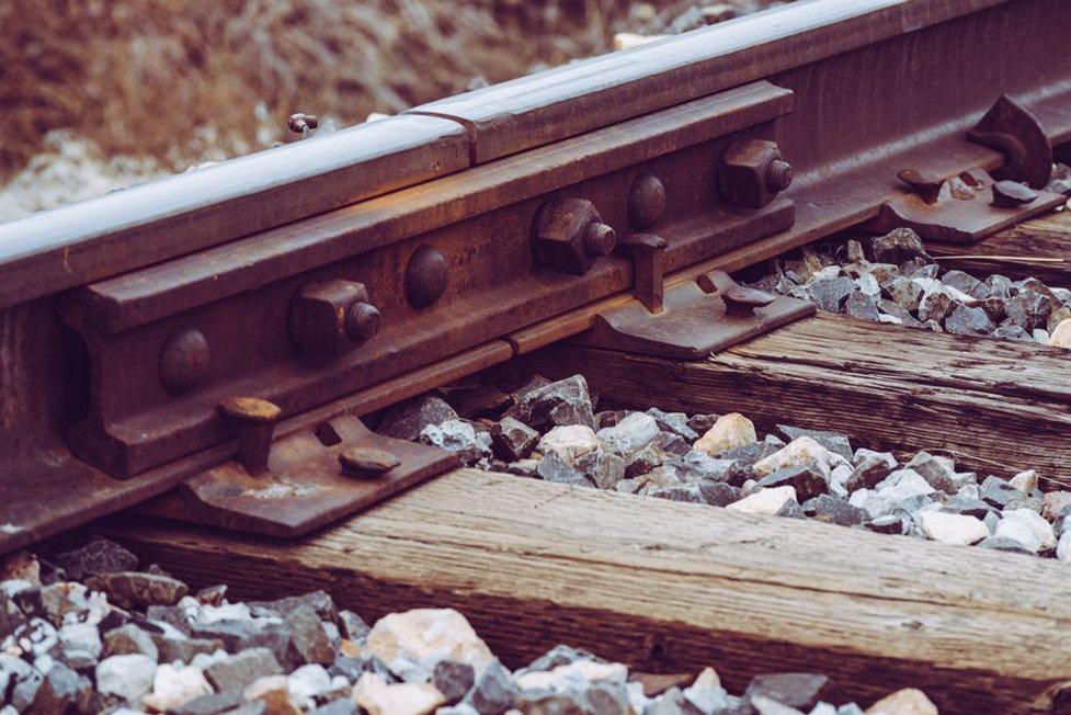
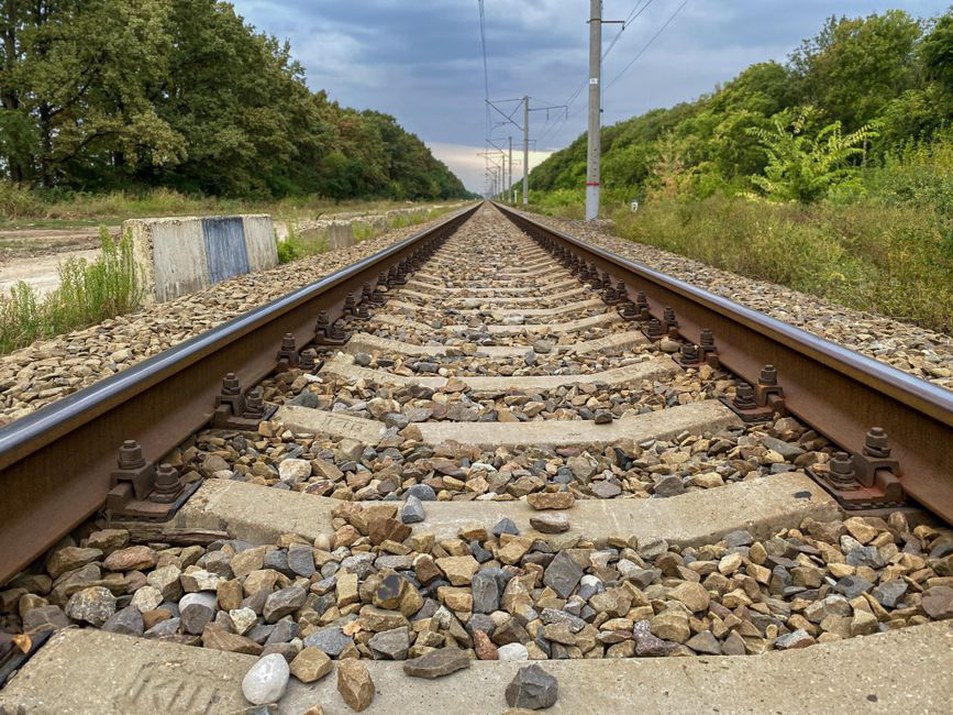
Railway loads pass through several layers, each with a distinct mechanical role. Rails and sleepers distribute wheel forces into the ballast. Ballast transfers load while providing resilience and drainage. Sub-ballast, blanket, or protection layers regulate stresses and limit contamination. The formation and underlying natural ground provide long-term support. Earthworks, culverts, retaining structures, bridge transitions, and drainage assets belong to the same geotechnical system.
The critical issue is often not one weak layer, but the contrast between adjoining zones. A stiff bridge approach beside a compressible embankment, a well-drained cutting next to a wet low embankment, or a repaired formation adjacent to untreated fine-grained soil can all cause differential movement. Track maintenance may restore the surface for a time, but it does not remove the cause of recurrent settlement.
What “stability” means in railway geotechnics
For a railway foundation, stability includes several connected requirements:
- Strength: soils and fills must resist shear failure, excessive lateral spread, bearing failure, and local punching beneath concentrated load paths.
- Deformation control: total settlement and, in particular, differential settlement must remain compatible with the required track geometry and maintenance regime.
- Hydraulic performance: water must be intercepted, conveyed, and discharged without saturating or eroding the formation.
- Durability under cyclic loading: repeated train passages can densify granular layers, break ballast, pump fines, and accumulate strain in susceptible subgrades.
- Resilience: the system must maintain safe performance through wet periods, flooding, freeze–thaw, drought shrinkage, seismic shaking where relevant, and changes in traffic loading.
Ground conditions that govern performance
A dependable ground model brings together geological history, groundwater conditions, material variability, and the operational demands of the line. Boreholes, trial pits, laboratory testing, in situ testing, geophysical methods, and inspection of existing earthworks may all be useful, but no single source should be read in isolation. Samples from soft clay can be disturbed. Widely spaced boreholes may miss lenses of peat or loose fill. Groundwater levels recorded on one day may bear little resemblance to seasonal peaks or perched water after prolonged rainfall.
Fine-grained soils
Clays and silts can provide adequate support when their stress history, drainage condition, and moisture sensitivity are understood. Soft, normally consolidated clay may consolidate substantially after embankment construction. Overconsolidated clay may be stronger, yet can soften where fissures admit water. Shrink–swell clay can move as seasonal moisture levels change. Low-plasticity silt warrants particular attention because it may lose stiffness when wet and can allow fines to migrate into ballast or drainage layers.
Granular soils and rock
Dense sand and gravel often provide good drainage and stiffness. Loose, saturated material, however, can settle under vibration or lose strength through liquefaction under certain earthquake conditions. Rock foundations require more than a compressive-strength value. Weathering, joint orientation, infilled discontinuities, karst voids, and water pathways may govern local movement. In cuttings, the main concern may shift away from foundation compression towards block instability, erosion, and drainage along discontinuities.
Made ground and organic deposits
Historic fill is inherently variable. It may contain rubble, ash, organic material, weak pockets, or undocumented services, and its behaviour can change over short distances. Peat and organic soils commonly combine high water content, low stiffness, and long-term compressibility. Their presence should influence alignment, embankment staging, the evaluation of ground treatment, and the monitoring strategy rather than being treated as a routine material classification.
Water is often the initiating factor
Water alters effective stress, softens some soils, transports fines, and creates pore pressures that reduce shear strength. A formation that performs adequately in dry weather may deteriorate quickly after a drainage blockage or a succession of wet seasons. Track drainage is therefore part of the structural performance of the railway, not an ancillary feature.
Common pathways include surface runoff entering ballast shoulders, seepage from uphill ground into cuttings, leaking utilities, concentrated culvert discharge, and groundwater rising into the formation. Under cyclic loading, fine particles can migrate upward into ballast, a process often described as mud pumping or slurry pumping. Wet spots, fouled ballast, rapid loss of level, and frequent tamping should prompt an investigation into water sources and filter compatibility rather than ballast renewal alone.
Drainage design and maintenance must consider the complete flow route: capture, filtration, collection, conveyance, outfall condition, and access for cleaning. A correctly sized drain that is blocked, crushed, or discharges onto an erodible slope cannot provide dependable control.
Load repetition and the track–ground interaction
Railways impose millions of load cycles. Stress magnitude and frequency depend on axle load, traffic mix, speed, wheel condition, sleeper spacing, ballast condition, and track geometry. A defect in one element affects the response of the others. A dipped joint or local void beneath a sleeper, for example, increases the force transmitted to the trackbed. That higher force can crush ballast and increase strain in an already weak formation.
Static calculations remain necessary, but they do not fully represent the interaction between track and ground. Geotechnical assessment must consider stiffness as well as strength, since abrupt stiffness changes cause differential deflection and greater impact loading. Transition zones near structures need specific attention. Approach slabs, engineered fills, drainage continuity, and staged construction may reduce the discontinuity, but their suitability depends on verified ground behaviour.
Common failure mechanisms and early indicators
| Mechanism | Typical signs | Underlying geotechnical concern |
|---|---|---|
| Progressive settlement | Repeated loss of level, local speed restrictions, frequent tamping | Consolidation, compressible fill, weak formation, or ballast intrusion |
| Differential movement | Twist defects, recurring transition dips, uneven sleeper support | Variable strata, unequal drainage, abrupt stiffness changes |
| Formation softening | Wet ballast, pumping fines, rapid geometry deterioration after rain | Saturation, poor filtration, inadequate drainage paths |
| Embankment instability | Cracks, bulging toes, lateral displacement, distressed drains | Raised pore pressure, erosion, weak foundation, surcharge effects |
| Frost-related deformation | Seasonal heave and thaw weakening | Frost-susceptible soil, water supply, inadequate thermal protection |
Operational records are a valuable diagnostic source. Repeated geometry defects at the same chainage, clusters of wet-bed reports, recurring maintenance interventions, and changes in ride quality can indicate a ground problem before displacement becomes visually obvious. These records should be reviewed alongside weather, drainage maintenance, and traffic history. What appears to be an isolated defect may coincide with a particular rainfall event, culvert blockage, or renewal boundary.
Investigation that supports defensible decisions
A staged investigation is usually more effective than applying the same test programme everywhere. Desktop review should identify former watercourses, historical maps, aerial imagery, old construction records, previous maintenance locations, mining or landfill records, and terrain changes. A walkover inspection can then identify seepage, cracking, blocked outlets, erosion, vegetation patterns, and inaccessible drainage features.
Intrusive work should target the suspected mechanism and extend deep enough and wide enough to define the relevant ground volume. For recurrent track settlement, the investigation may need to establish ballast condition, formation thickness, subgrade strength, groundwater conditions, and the presence of deeper compressible strata. Where an embankment is moving, boreholes and instrumentation may need to extend below the potential failure surface rather than stopping at formation level.
Laboratory and field tests should be chosen for their value in making decisions. Index classification alone cannot establish settlement rate, cyclic susceptibility, permeability, or shear-strength behaviour. Equally, sophisticated testing has limited value if samples are unrepresentative or results are interpreted without a coherent geological model.
Interventions should match the mechanism
Effective remediation begins by separating symptoms from causes. Tamping restores geometry and may be appropriate as a short-term operational measure, but it is not necessarily a permanent remedy. Ballast cleaning can improve drainage and resilience where fouling is the main issue, yet it will not address continuing groundwater inflow or deep consolidation settlement.
Depending on site conditions, options may include drainage rehabilitation, filter and separation layers, improved formation materials, geosynthetic reinforcement, local excavation and replacement, embankment reprofiling, ground improvement, staged loading, retaining measures, or structural support solutions. Each measure changes load paths and water paths. It should be assessed for constructability within railway possessions, effects on adjacent assets, inspection access, and long-term maintenance requirements. Selection requires site-specific design by competent geotechnical and track engineers, supported by verified parameters and risk assessment.
Monitoring as a control system
Monitoring is most useful when it addresses a defined engineering question. Settlement plates or precise levelling can measure vertical movement. Inclinometers can identify lateral shear zones, piezometers indicate pore-pressure response, track geometry data records the operational effect, and remote sensing can help screen long corridors for movement trends. Instrument selection, baseline readings, trigger levels, review responsibilities, and response actions should be agreed before construction or before a period of expected instability.
At sites exposed to earthquake shaking, assessment should also consider cyclic softening, slope deformation, settlement of loose saturated soils, and whether drainage and retaining elements can continue to function. The related discussion of seismic design codes for transport infrastructure and their key checks provides useful context for translating seismic hazards into verifiable infrastructure requirements.
A practical verification sequence after remedial work
- Record baseline track geometry, drainage condition, groundwater or pore pressure where relevant, and visible earthwork features.
- Confirm through hold points and material records that installed layers, drains, filters, and reinforcement match the verified design intent.
- Inspect outlets and adjacent slopes after the first significant rainfall events, rather than only at construction completion.
- Compare early track-maintenance demand with the pre-intervention pattern and investigate any persistent local recurrence.
- Continue monitoring long enough to capture the governing response, such as consolidation, seasonal wetting, or a representative traffic period.
At a repaired wet-bed location, an acceptance record may combine a post-work drainage inspection with repeat geometry measurements after heavy rainfall and after a defined traffic interval. If water returns at the ballast shoulder or the same local dip reappears, the appropriate next step is to trace the hydraulic pathway and verify the formation profile before scheduling another surface-only correction.