A heavier axle loads more than the rail. The extra force passes through the rail seat, sleepers and ballast before it reaches the formation soil. Excessive deformation in any layer can disturb track geometry, raising impact loads and speeding deterioration elsewhere. Capacity therefore has to be judged against the proposed vehicle load, speed and traffic volume, as well as the maintenance demand the railway can accept. A stronger rail section alone cannot establish it.
Define what capacity means
Axle load is the static weight assigned to an axle; it is not a fixed measure of the force the track experiences as a wheel passes. Speed, wheel and rail irregularities, suspension behaviour and changes in support stiffness all affect that force. Repetition matters as much as a single passage: a track may carry one heavy test vehicle yet settle rapidly under regular traffic.
Three limits need separate consideration. Strength concerns component damage or failure under an extreme load. Serviceability concerns deflection, alignment and ride quality in normal operation. Long-term performance concerns fatigue, wear, ballast degradation and permanent ground deformation. Improving one does not necessarily improve the others. The basic roles of rails, sleepers, ballast and subgrade are outlined in Wikipedia’s overview of railroad track construction; the capacity question lies in how those parts respond together.
Follow the load through the track
Rail and fastening system
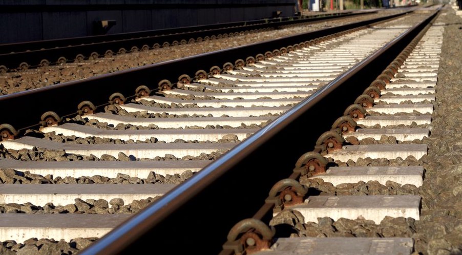
The rail bends between sleeper supports and spreads a wheel load over several sleepers. Rail section, steel condition and support spacing affect bending stress and deflection. Wheel–rail contact places a separate limit on capacity: a heavier wheel load can worsen surface damage even if bending strength is adequate. On curves, lateral forces also make rail restraint and gauge retention more demanding.
Fastenings must retain the rail while accommodating the forces and movements expected in service. Rail size alone says little about whether they can do so. Pads influence load transfer into the sleepers; a more compliant pad may moderate some contact forces but also alter rail deflection and the response to passing wheels. Rail, fastenings and pads need to be assessed together.
Sleepers, ballast and formation
Sleepers maintain gauge and spread load into the ballast. Their spacing, stiffness and bearing condition affect how evenly that load is shared. Ballast distributes it further, provides lateral restraint and permits geometry correction by tamping. Particle quality, grading, confinement and drainage govern how well it performs. Fouled or saturated ballast may drain poorly and leave the track unevenly supported.
A sub-ballast or protective layer, where present, can separate materials and help manage water. Beneath it, the formation and underlying ground receive the load. Weak, variable or moisture-sensitive soils may accumulate permanent strain with each axle passage. Strengthening an upper component will not stop settlement in an inadequate foundation; the visible defect may simply appear elsewhere.
Investigate the controlling locations
Capacity is seldom uniform along a corridor. Bridge approaches, culverts, level crossings, turnouts and cut-to-fill transitions can bring abrupt changes in support stiffness. A soft spot may allow greater rail deflection and ballast movement; next to a rigid structure, differential movement can produce impact loads. Curves and grades add lateral or longitudinal demands. Each potential controlling location needs its own assessment rather than a corridor-wide condition rating.
Track geometry history, visual inspection, component condition, drainage observations and ground information provide a starting point. Deflection measurements or other load-response tests can help identify uneven support, although results depend on the test vehicle, speed and moisture conditions. A substantial proposed load increase may warrant targeted intrusive investigation to establish layer thicknesses, material condition and formation properties.
Water needs particular scrutiny. Blocked outlets, water trapped at the ballast shoulder or poor formation drainage can change support after rain or seasonal thaw. On embankments, the effects of increased traffic demand must also be considered alongside ground movement and overall stability. The investigation approach described for geotechnical assessment of transport slopes is relevant where the track foundation and adjacent slope behave as one ground system.
Match interventions to the mechanism
There is no fixed upgrade sequence. Treatment depends on whether the controlling problem is component strength, contact damage, loss of geometry or foundation deformation. Options include:
- Rail and fastening renewal: addresses inadequate section, deteriorated rail or restraint problems, provided the supporting layers can carry the changed loading.
- Sleeper replacement or spacing changes: can improve gauge retention and load distribution, but may expose weak ballast or formation support.
- Ballast cleaning or renewal: restores drainage and support where fouling or degradation is the main problem.
- Formation treatment: addresses persistent deformation beneath the ballast; the choice requires site-specific ground assessment and constructability checks.
- Drainage correction: tackles recurrent weakening rather than repeatedly correcting the geometry defect it causes.
Interventions can change where the track is most vulnerable. A stiffer structure may reduce deflection locally while concentrating loads at an untreated transition. Cleaner or deeper ballast may achieve little if fine soil migrates upward or water has no outlet. On an operating railway, excavation depth, access, possession duration and verification of hidden work also affect whether a proposed treatment is practical.
Check repeated loading and verify the result
Assessment should reflect the proposed traffic pattern, not just the largest axle load. More trains mean more stress cycles and potentially shorter intervals between geometry corrections. At higher speed, even a small irregularity can produce a more significant impact. Established track design methods or numerical models may be appropriate, but their assumptions must reflect measured support and realistic vehicle loading. Sensitivity checks help where formation stiffness, water level or future traffic is uncertain.
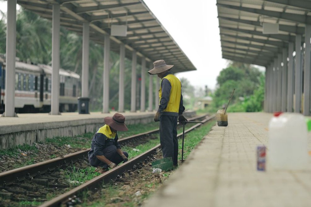
Acceptance after construction should confirm what was installed and how the completed track behaves. Material records, layer thickness checks, compaction evidence where applicable and drainage inspections document the work. Geometry and load-response measurements establish an initial performance reference; later surveys can show whether movement is normal bedding-in or a recurring weak spot.
At a bridge approach due to carry heavier freight, that reference might include a short profile across the structure–earthwork transition. Record geometry and support response after the work, then repeat the measurements under comparable loading and environmental conditions. A dip developing at the same chainage tells the engineer more about that transition than a corridor-wide average geometry score.