Bridge failures during floods often begin below the waterline. Fast-moving water removes bed material around piers and abutments, reducing foundation support. Debris can then lodge against the structure, increase hydraulic loading, and redirect the current toward vulnerable banks. Flood resistance is therefore not achieved by strengthening the superstructure alone. It depends on hydraulic, geotechnical, structural, and operational measures that account for how the river may change during an extreme event.
The governing condition is rarely the channel seen during a routine site visit. Design must consider flood discharge, velocity, water-surface elevation, sediment transport, channel migration, floating debris, and erosion that may continue after peak flow. Because these processes interact, span arrangement, foundation depth, approach embankments, and river-training works should be developed from a shared site model rather than treated as separate disciplines.
Start with the flood mechanism, not the bridge type
Flood hazards vary markedly between catchments. A steep, confined mountain stream may generate high velocities, coarse bedload, boulders, and rapid local scour. A low-gradient alluvial river may migrate laterally, form bends and bars, and erode an approach embankment before the main channel reaches the bridge. Coastal and tidal crossings may be exposed to surge, waves, backwater, and debris carried over a broad area. Urban crossings can be affected by upstream culverts, development, and runoff peaks that arrive faster than in a natural basin.
An early hazard model should identify the processes that could cause loss of service or structural failure:
- Contraction scour when the crossing or floodplain encroachment accelerates flow through a reduced opening.
- Local scour at piers, abutments, guide banks, retaining elements, and exposed foundation components.
- Long-term degradation or aggradation of the channel bed, altering foundation exposure and hydraulic capacity over time.
- Lateral channel migration that directs the main current toward an abutment or bypasses the intended opening.
- Debris and ice blockage that reduces effective waterway area and creates asymmetric loading.
- Approach washout where overtopping, seepage, or erosive floodplain flow removes roadway fill and pavement support.
- Buoyancy, hydrodynamic, wave, and impact actions on low-level decks, bearings, piers, utilities, and protective works.
Historical evidence is often as valuable as a short field campaign. Multi-year aerial imagery, maintenance records, gauging data, post-flood photographs, local observations of sediment movement, and documented high-water marks can reveal channel behaviour that a limited survey may miss. The wider interaction between drainage, changing rainfall patterns, and ground response is discussed in this blog’s analysis of climate change risks for transport infrastructure, including flood and drainage resilience.
Hydraulic layout: preserve the river’s conveyance
The most effective way to reduce scour demand is often to avoid creating it. A crossing should provide an adequate, hydraulically efficient waterway for the governing design events, with realistic assumptions about floodplain flow and debris. Where practical, locating piers outside the active main channel reduces obstruction. That choice must still be balanced against span economy, constructability, and foundation conditions.
Bridge alignment should follow the predominant flood flow where possible rather than forcing water through a skewed, constricted opening. Severe skew can produce concentrated velocities, abutment vortices, and uneven pier loading. If a skewed crossing is unavoidable, hydraulic modelling should assess the resulting flow field and identify where armoring, guide banks, relief openings, or other measures are justified.
Floodplain connectivity and relief openings
Approach embankments can act as unintended dams. They may obstruct floodplain conveyance, raise upstream water levels, concentrate flow at abutments, and direct erosive water along the road corridor. Relief structures or extra openings can reduce these effects where floodplain hydraulics demonstrate a need. Their design still requires outlet protection, erosion control, and an assessment of whether newly concentrated flow transfers risk elsewhere.
Freeboard is more than clearance above the expected water depth. It should account for floating debris, anticipated bed changes, wave action where relevant, uncertainty in hydraulic predictions, and acceptable performance during rare events. In some settings, a low deck may be designed for controlled overtopping. That decision requires explicit consideration of buoyancy, uplift, bearing restraint, deck anchorage, approach erosion, closure procedures, and post-flood inspection.

Scour-resistant foundations and substructure
Scour assessment should distinguish between general channel change, contraction scour, and local scour. Treating all effects as a single combined value can be overly conservative in some cases and dangerously incomplete in others. The design team needs a defensible estimate of the bed elevation that could occur during and after the relevant flood sequence, then must verify that foundation capacity and structural integrity remain adequate at that level.
Deep foundations are commonly used where predicted scour could expose shallow support. Piles and drilled shafts need assessment for axial capacity, lateral resistance, unsupported length, group effects, and loss of surrounding soil during scour. A foundation may remain vertically supported while still developing unacceptable lateral deflection or bending after scour removes near-surface confinement. Connections between pile caps, columns, shafts, and the superstructure must retain a clear load path under these altered boundary conditions.
Abutments require equal attention
Abutment failures are often linked to eroded approach fills, toe scour, and concentrated flow around the embankment end. Setback abutments, spill-through slopes, mechanically stabilized approach systems, and protected guide banks may each suit different site conditions. Selection depends on hydraulic attack angle, floodplain width, soil type, embankment geometry, expected inundation duration, and access for inspection.
Rock riprap, concrete blocks, articulated mattresses, grouted systems, and vegetated measures can provide erosion protection, but all require suitable filter design and toe treatment. Without a compatible granular or geotextile filter, an outer protective layer may allow fine material to escape through piping or winnowing. A revetment that ends without a buried toe can be undermined as the bed scours at its edge. Materials must be sized for expected hydraulic forces and installed with attention to gradation, thickness, bedding, transitions, and construction damage.
Rigid armoring is not always appropriate. It may shift erosion downstream or increase local turbulence if it disrupts the natural channel form. Nature-based bank stabilization can improve long-term performance on lower-energy reaches, particularly when paired with floodplain restoration and set-back infrastructure. It should not be assumed capable of resisting deep, high-velocity, debris-laden flow without site-specific evidence.
Design for debris, impact, and accidental actions
Debris can govern flood performance even where the clear-water opening appears adequate. Large wood, vegetation, shipping materials, vehicles, and damaged upstream structures may lodge on piers or beneath a low deck. Blockage increases drag, raises upstream water levels, and can initiate scour at locations that were not critical in a clear-water model.
Useful measures include reducing the number of in-channel piers, selecting pier forms that are less likely to snag debris, orienting pier noses with the flow, and providing suitable clearance. Sacrificial debris-control measures should be placed only where their failure or blockage will not worsen the bridge hazard. Debris racks need particular caution: they require accessible maintenance, defined loading assumptions, and a safe failure philosophy. A neglected rack can become the obstruction it was meant to control.
Substructure components also need resistance to collision and hydrodynamic actions appropriate to the crossing. On navigable waterways, vessel collision is a separate but related hazard. Coastal and estuarine bridges may need to account for wave impact, storm surge, corrosion exposure, and repeated wetting and drying. Bearings, expansion joints, drainage details, and utility attachments should be located or protected so flood-borne material cannot disable components needed for structural movement or roadway safety.
Approaches, drainage, and continuity of service
A bridge may remain structurally intact while the route fails because its approaches have eroded. The deck-to-embankment transition brings together several vulnerabilities: settlement, differential movement, overtopping, pavement damage, embankment toe scour, and blocked drainage. Flood-resilient approaches need positive drainage paths so water is not trapped behind retaining elements or discharged onto unprotected slopes.
Both surface and subsurface water routes should be checked. Culverts, side ditches, downpipes, outlet channels, and drainage layers need maintainable inlets and protected outlets. During prolonged inundation, seepage through an embankment can reduce effective stress, cause internal erosion, or destabilize slopes as floodwater recedes. Filters, drainage blankets, cutoff measures, and relief provisions should follow geotechnical investigation and seepage analysis rather than being added as standard details.
Where rapid reopening after a flood is an operational objective, resilience criteria should extend beyond avoiding collapse. Relevant considerations may include acceptable repair time, detour availability, replaceable sacrificial components, stockpiled protection material, and access for emergency inspection. These are asset-management decisions as much as structural decisions.
Use modelling as a decision tool, with explicit uncertainty
Hydrologic and hydraulic models are essential, but numerical precision should not be mistaken for certainty. Flood estimates may be uncertain because of limited records, land-use change, reservoir operations, changing rainfall patterns, sediment shifts, or poorly defined tributary inflows. Hydraulic results are sensitive to terrain data, roughness assumptions, boundary conditions, bridge geometry, blockage assumptions, and representation of the channel bed.
A sound workflow tests plausible scenarios rather than relying on one deterministic water level. These can include a larger-than-expected flood peak, partial debris blockage, a shifted thalweg, a degraded channel bed, compromised bank protection, and simultaneous tributary or tidal effects. Two-dimensional hydraulic modelling is particularly useful when floodplain flow, bridge skew, multiple openings, or complicated approach geometry create lateral variation that one-dimensional methods cannot represent adequately. Physical modelling may be justified for unusually complex crossings with serious consequences of failure.
| Design question | Evidence or analysis needed | Typical response |
|---|---|---|
| Will flow concentrate at an abutment? | Floodplain topography, 2D velocity field, observed high-water paths | Modify opening layout, protect slopes and toe, add controlled relief capacity where justified |
| Can foundations tolerate scour? | Channel morphology, sediment data, scour assessment, geotechnical capacity after soil loss | Increase embedment, revise foundation system, or reduce scour demand through layout changes |
| What happens if debris blocks an opening? | Debris history, clearance geometry, blockage scenarios, structural loading checks | Increase clearance, simplify pier arrangement, provide maintainable debris management measures |
| Can the route reopen quickly? | Approach overtopping paths, drainage capacity, repair access, inspection requirements | Protect approach interfaces, improve drainage and outlet protection, plan inspection and repair resources |
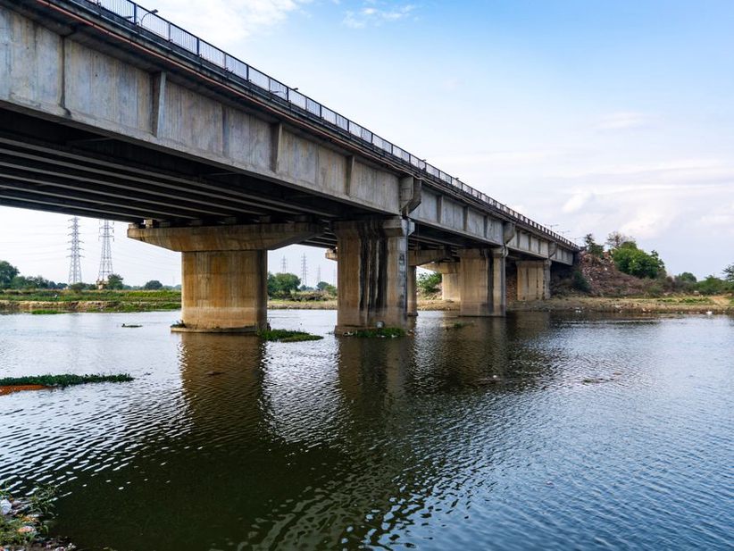
Monitoring and inspection turn design assumptions into managed risk
No calculation removes the need to observe an active river. Baseline surveys of channel cross-sections, bed elevations, bank lines, and protective works provide a reference for identifying change. After significant floods, inspections should check for displaced armor, exposed filters, settlement behind abutments, debris accumulation, damaged drainage outlets, cracking or movement in retaining systems, and signs of undermining.
Instrumentation may be justified for high-consequence crossings or sites subject to rapid morphological change. Water-level sensors, rainfall gauges, cameras, tilt sensors, accelerometers, and scour-monitoring devices can support operational decisions. Their value depends on defined thresholds, reliable telemetry, maintenance, and personnel able to interpret alarms. A sensor network without inspection procedures or authority to act does not reduce risk.
Build inspection access into the layout
Details should allow safe examination of bearings, pier surfaces, visible foundation elements, drainage outlets, and armoring. Access routes for inspection crews and emergency equipment can determine whether developing scour is identified early or only after service is disrupted. Removable deck panels, protected bank access, and clear inspection zones may add initial cost but reduce the time needed for later intervention.
For a bridge with known scour susceptibility, the flood action plan should define the trigger for closure or restricted use, responsibility for reviewing water-level and weather data, the sequence of post-event inspections, and the conditions for reopening. The final check should compare surveyed bed elevations at each critical pier and abutment with the design scour reference level, rather than relying solely on a visual inspection from the deck.