A highway cut may appear stable when construction ends, then become unsafe after one wet season. Infiltration can raise pore-water pressure along a weak layer and reduce the soil’s available shear strength. Slope stability is therefore not a matter of inclination alone. It depends on the ground profile, groundwater regime, construction sequence, loading at the crest and toe, drainage performance, and the consequences of movement for the road corridor.
For highway engineers, the objective is not limited to preventing a major landslide. Even small movements can crack pavement, block ditches, distort barriers, reduce sight distance, or trigger progressive failure in retaining systems. A defensible design identifies credible failure mechanisms, accounts for uncertainty in ground conditions, and selects drainage, geometry, reinforcement, or support measures that address those mechanisms.
What slope stability means in a highway corridor
Slope stability is the ability of natural or constructed ground to resist movement under gravity and applied loads. In engineering practice, it is often expressed as a factor of safety: the ratio of resisting forces or moments to those driving movement. The calculation is useful only when the geological model and assumed water conditions are credible.
Highway slopes generally fall into several categories:
- Cut slopes, formed when excavation removes material to create the road platform.
- Embankment slopes, constructed from compacted fill placed above natural terrain.
- Natural slopes, which may be affected by widening, drainage changes, toe excavation, or surcharge from the road.
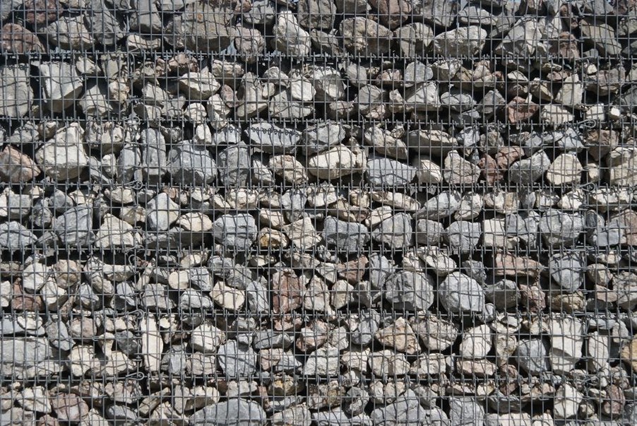
- Retained slopes, supported by walls, reinforced soil, piles, anchors, or other structural systems where geometry alone is insufficient.
The critical slip surface may be shallow and nearly parallel to a cut face, rotational and deep-seated in cohesive soils, or controlled by bedding, joints, faults, and weathered seams in rock. A circular analysis may suit some soil slopes but can be misleading where failure is controlled by structural discontinuities.
Ground investigation must resolve the failure mechanism
Geotechnical investigation along a road alignment must establish more than general soil classifications. The design team needs a ground model that explains how materials are arranged, where weak horizons occur, how weathering changes with depth, and how water moves through the slope. Boreholes, trial pits, mapping, geophysical surveys, laboratory testing, and in-situ testing each address different uncertainties.
Geology and structure
In soil, important features may include soft clay seams, loose saturated sand lenses, organic deposits, colluvium, and interfaces between fill and natural ground. In rock, engineers assess bedding, foliation, joint sets, fault zones, discontinuity persistence, infill materials, and their orientation relative to the slope face. A rock mass can test strong in intact specimens yet remain susceptible to planar sliding, wedge failure, or toppling along discontinuities.
Mapping should extend beyond the immediate road footprint. Scarps, hummocky ground, tension cracks, tilted trees, displaced drainage lines, and irregular benches can indicate old landslide deposits. Such evidence matters because reactivation of an existing mass may require different controls than failure confined to a newly excavated cut.
Groundwater and seasonal change
Water is often the dominant factor in slope performance. It increases unit weight, produces seepage forces, erodes exposed soil, and raises pore pressure, reducing effective stress and shear resistance. Groundwater levels measured during a short investigation may not represent prolonged rainfall, snowmelt, reservoir fluctuation, blocked drainage, or construction-period conditions.
Piezometers installed at selected depths can distinguish perched water from deeper aquifers and show delayed responses to rainfall. Their readings should support hydrogeological interpretation rather than be treated as a single fixed water table. Broader climate-related changes in rainfall intensity and drainage loading also affect corridor resilience; they are considered in Adapting Transport Infrastructure to Climate Change Challenges.
Loads and disturbances introduced by the highway
Road construction changes the stress state of a slope. Cutting steepens the face and may remove toe support. Filling adds surcharge to compressible or weak ground. Temporary stockpiles, construction traffic, cranes, and staged earthworks can create critical short-term conditions even where the final arrangement is stable.
Traffic loads are normally distributed through pavement and earthworks, but heavy vehicles near a crest, barriers founded close to an edge, and local widening can matter where slopes are marginal. Vibration and cyclic loading require separate consideration from static surcharge; Understanding Dynamic Loads in Road Infrastructure explains how repeated loads affect road systems.
Seismic loading may govern in areas of significant seismic hazard, particularly for loose saturated soils, sensitive clays, high embankments, and retaining structures. Assessment should consider the project-specific hazard, expected deformation tolerance, possible strength loss, and the need to maintain emergency access after an event rather than relying solely on a static factor of safety.
Analysis methods and their limits
Limit equilibrium methods remain widely used because they can examine multiple potential slip surfaces and provide a transparent factor of safety. Methods of slices can account for layered ground, pore pressures, surcharges, and reinforcement, provided the assumed interslice forces and failure geometry are appropriate. Their main limitation is that they do not directly represent stress-strain behaviour or progressive deformation.
Finite-element or finite-difference analysis can be useful where construction staging, deformation, complex geometry, interaction with structures, or nonlinear material behaviour controls the problem. These methods can estimate displacement patterns and pore-pressure response, but they depend on suitable constitutive models and credible input parameters. Sophisticated software cannot compensate for inadequate investigation.
| Condition | Likely concern | Assessment emphasis |
|---|---|---|
| Steep soil cut after rainfall | Shallow or rotational slip | Strength profile, seepage, erosion, surface drainage |
| Rock excavation with dipping beds | Planar or wedge sliding | Discontinuity orientation, persistence, water pressure, block geometry |
| High embankment on soft ground | Foundation failure or excessive settlement | Undrained strength, staged loading, consolidation, lateral movement |
| Existing landslide crossed by widening | Reactivation of deep movement | Slip surface depth, groundwater regime, monitoring, toe and crest effects |
Parameter selection should distinguish between drained and undrained conditions, peak and residual strength where relevant, and intact versus remoulded or weathered material. Residual strength can control behaviour in old landslides and sheared clay seams. Sensitivity studies are essential: varying water levels, shear strength, surcharge, and geometry identifies the uncertainties that actually control the design decision.
For a concise description of landslides and their geological context, Encyclopaedia Britannica’s overview of landslides provides useful background terminology. Engineering design, however, must rely on site-specific investigation and applicable authority requirements.
Stability controls: prioritize water and geometry
The most reliable intervention is often to reduce driving forces before introducing structural support. Flattening a slope, creating benches, removing unstable material, or avoiding a problematic alignment can reduce long-term reliance on complex systems. Space, environmental constraints, and right-of-way limitations may restrict these options, but they should be considered early.
Drainage systems
Surface drainage should stop runoff from flowing over an exposed face or infiltrating behind a crest. Typical elements include lined crest channels, berm drains, down-drains, ditch protection, and controlled outlets that do not discharge onto erodible ground. The full flow path matters: a well-designed ditch that discharges at an unprotected outlet merely moves the problem downhill.
Subsurface drainage may include horizontal drains, drainage blankets, toe drains, chimney drains in embankments, or drainage layers behind walls. The aim is to reduce pore pressure and collect water safely. Filters and drainage media must limit the migration of fine particles; clogged drains or missing filters can defeat the intended control.
Reinforcement and retaining systems
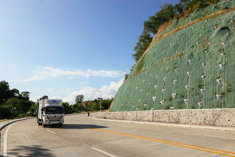
Soil nails, ground anchors, reinforced earth, piles, retaining walls, and rock bolts can provide resistance where regrading and drainage do not achieve the required performance. Selection depends on failure depth, load path, constructability, corrosion exposure, inspection access, and the consequences of partial degradation. Shallow soil nailing, for example, cannot address a deep-seated failure mechanism extending well below nail length.
Rockfall barriers and mesh serve a different purpose from global stabilization. They manage detached blocks and local ravelling but do not necessarily prevent movement of the overall rock mass. Drawings, risk assessments, and maintenance plans should clearly distinguish debris containment from slope stabilization.
Construction sequencing and quality control
A slope design can fail during construction if excavation proceeds too quickly, drainage is delayed, or fill placement does not meet the assumed density and moisture conditions. Temporary works require their own stability assessment. This is especially important for staged embankments on soft soils, deep cuts with changing support conditions, and slopes exposed during wet seasons.
- Confirm exposed ground conditions against the design model as excavation progresses.
- Install permanent and temporary drainage early enough to control water during earthworks.
- Place fill in controlled lifts and verify compaction, moisture condition, and material conformity.
- Inspect reinforcement, filter layers, anchors, and drains before they become inaccessible.
- Define hold points for unexpected seepage, weak material, cracking, or deformation.
Observational methods may be appropriate where uncertainty remains, behaviour can be monitored, and pre-agreed actions are practical. They require baseline readings, trigger levels, clear responsibility, and the ability to slow, modify, or stop construction. Monitoring without an action plan is data collection rather than risk control.
Inspection and monitoring in operation
Operational inspection should focus on signs of changing water conditions and movement: new pavement cracking near a slope crest, shoulder settlement, bulging at the toe, blocked ditches, seepage stains, displaced walls, open joints, erosion gullies, and fallen rock. Inspections after intense rainfall, freeze-thaw cycles, earthquakes, wildfire, or drainage repairs can reveal changes missed by routine schedules.
Instrumentation may include inclinometers for lateral deformation, piezometers for pore pressure, settlement plates, survey targets, extensometers, anchor load cells, and remote sensing where the corridor scale warrants it. Interpretation should compare trends with rainfall, construction activity, and drainage performance. A single elevated pore-pressure reading may matter less than a sustained rise combined with accelerating displacement.
When a slope shows distress, the initial field response is usually to establish safe access, control traffic exposure where necessary, inspect drainage and erosion, and obtain engineering assessment before removing material or placing counterweight fill. Unplanned toe excavation, clearing a blocked channel without controlling runoff, or loading the crest with emergency equipment can worsen an active mechanism. A useful investigation record notes the location and timing of cracks, measured widths, seepage condition, recent weather, drainage changes, and photographs from repeatable viewpoints. Those details allow engineers to update the stability model on evidence rather than assumption.