
A railway embankment can become unsafe well before a slope visibly collapses. Small changes in track alignment, recurring ballast fouling, blocked side drains, fresh tension cracks above a cutting, or wet areas appearing on a slope may all indicate that ground movement is affecting the formation. Because rail traffic applies repetitive loads and depends on tight geometric tolerances, even limited deformation may require speed restrictions or closure.
Landslide risk is therefore not confined to dramatic failures in steep mountain terrain. It can arise wherever geology, groundwater, terrain modification, drainage, and rail operations combine to create a credible slope-movement mechanism. Managing that risk calls for an understanding of ground conditions across the corridor, detailed investigation at critical locations, practical control measures, and monitoring that supports timely operational decisions.
Why railway corridors are particularly vulnerable
Railways often follow valleys, river terraces, coastlines, and mountain passes to limit gradients and earthworks. These landforms can contain variable superficial deposits, weathered rock, colluvium, old landslide masses, and complex groundwater pathways. A route may also be constrained between a cut slope on one side and a fill slope, watercourse, or retaining structure on the other, leaving little capacity to accommodate deformation.
Track performance depends on the stability of the entire support system: rails, fastenings, sleepers, ballast, sub-ballast, formation layers, embankment, and natural foundation. Differential movement at any level can cause uneven settlement, lateral track displacement, loss of cross-level, and accelerated deterioration under traffic. A slope failure may also deposit debris on the railway, undermine the formation, block culverts, or damage overhead line and signalling assets.
The main loading and triggering factors often interact:
- Prolonged rainfall raises pore-water pressures and weakens unsaturated soils as suction is lost.
- Intense short-duration storms can overwhelm drains, erode gullies, and concentrate runoff at vulnerable points.
- Seasonal groundwater variation may reactivate old slip surfaces or soften weak strata.
- Excavation and embankment placement can alter slope geometry, remove toe support, or add driving load.
- Drainage defects may allow leakage from ditches, culverts, water mains, or track drainage systems.
- Weathering, freeze-thaw, and vegetation change can alter near-surface strength and water pathways.
- Seismic shaking can trigger rockfalls, reduce the strength of susceptible soils, and destabilize slopes that are already marginal.

Start with a corridor ground model, not isolated boreholes
A landslide mitigation strategy should begin before the final alignment and earthwork profile are fixed. Early desk studies should bring together topography, geological mapping, aerial imagery from different dates, historical maintenance records, drainage plans, geomorphological evidence, rainfall history, and reports of previous instability. Older imagery is particularly useful because regraded or vegetated slopes may conceal historic scarps, hummocky ground, displaced drainage lines, and former debris paths.
The engineering geological model should distinguish among hazard types rather than treating “landslide” as one condition. Relevant mechanisms include shallow translational soil slips, deep-seated rotational failures, debris flows, rockfalls, wedge or planar rock failures, embankment slips, and collapse or erosion around drainage structures. Each mechanism has different warning signs, investigation requirements, runout behaviour, and control measures.
Investigations should test the failure mechanism
Ground investigation should answer defined questions. Where is the likely slip surface? Which materials govern shear strength? How does groundwater move through the slope? What is the depth and condition of weathered rock? Is an apparently natural slope actually an old landslide deposit? Are weak layers dipping toward the railway?
A proportionate investigation may combine boreholes, trial pits, rotary coring, in-situ testing, laboratory classification and strength testing, geophysical surveys, groundwater monitoring, and engineering geomorphological mapping. Boreholes alone can miss lateral variability or narrow water-bearing features. Remote observations without intrusive verification, however, can misidentify material boundaries or groundwater conditions.
Locations and depths should be selected around the anticipated mechanism: the crest, body, and toe of the slope, drainage routes, and the railway formation itself. For existing or potentially reactivated deep movement, inclinometers and piezometers may provide more useful evidence than a dense pattern of shallow samples. For rockfall hazards, the key evidence includes discontinuity surveys, rock mass condition, catchment geometry, and likely block trajectories.
Design choices that prevent instability
The most effective intervention is often to avoid an unstable landform or reduce the extent of terrain disturbance. Refining the alignment can move the track away from an active slide, a steep colluvial hollow, or the runout zone below a rock face. Where rerouting is impractical, the design should show how each credible mechanism will be prevented, restrained, intercepted, or managed through operational controls.
Control water first and keep it controlled
Water is often the decisive factor in railway slope failures. Drainage should be designed as a connected system, not as a collection of separate ditches and pipes. Surface runoff should be intercepted above cut slopes where appropriate, conveyed without causing erosion, and discharged to a stable outlet. Track drainage, slope drainage, culverts, and natural watercourses need compatible levels and adequate access for inspection and cleaning.
Subsurface drainage can reduce pore-water pressure where ground conditions and the failure mechanism support its use. Options may include trench drains, horizontal drains, drainage blankets, and collector systems. Their performance depends on filter compatibility, gradients, outlet protection, and long-term maintenance. Poorly detailed trenches can become preferential flow paths, while blocked outlets can remove the intended benefit.
Construction sequencing also matters. Installing permanent drainage late in the works can leave exposed slopes vulnerable during wet periods. Temporary interception drains, sediment controls, protected discharge points, and rapid stabilisation of completed earthworks should be treated as safety-critical construction measures, not temporary conveniences.
Match slope geometry and support to ground conditions
Flattening a cut or fill slope reduces driving forces, but may not be sufficient or practical. Appropriate geometry depends on material variability, groundwater, stratigraphic orientation, seismic conditions where relevant, construction method, and the consequences of movement. Benches can aid drainage and access, but their arrangement must not collect water or create weak interfaces.
Where slope geometry alone cannot provide the required performance, support systems may include retaining structures, reinforced soil, stabilising berms, piles, anchors, soil nailing, rock bolts, mesh, barriers, or combinations of these measures. Selection should follow the expected failure mode and allowable deformation, rather than a standard detail. A rigid wall may protect the track locally while transferring loads to a weaker foundation. A rockfall fence may contain detached blocks, but it does not stabilise the source slope.
Embankments need equal attention. Their stability depends on foundation conditions, staged placement, compaction control, drainage, material quality, and toe support. Soft or compressible ground can cause settlement and lateral spreading that degrade track geometry without producing a conventional landslide. Instrumentation and observational methods may be essential where construction loading must be adjusted in response to measured pore pressure or deformation.
Construction-stage risk is a separate engineering problem
A slope that is stable in its completed form can fail during excavation, dewatering, blasting, or fill placement. Temporary cut faces, partial removal of toe material, stockpiles near a crest, construction traffic, and uncontrolled runoff all alter ground response. The contractor’s method statement should therefore be checked against the geotechnical design assumptions, including excavation sequence, allowable exposure duration, water management, temporary support, and inspection hold points.
Clear communication between the designer, contractor, and rail operator is needed when site conditions differ from those anticipated. Examples include unexpected weak seams, artesian water, substantially deeper weathering, unrecorded fill, or evidence of a historic slide. Such findings should prompt review by competent geotechnical personnel, rather than an improvised field change that could compromise the stability model.
Quality assurance should verify materials, lift thicknesses, compaction, reinforcement placement, drainage gradients, filters, pipe joints, outlet protection, and as-built locations. Drainage and buried stabilisation elements are difficult to inspect after completion, so records made during construction become part of the evidence available for future asset management.
Monitoring should support decisions, not merely collect data
Monitoring is most useful when tied to a clear observation plan. The plan should identify what is measured, why it is measured, the expected range of behaviour, who reviews the data, and what action follows if thresholds are exceeded. Useful tools include survey prisms, automated total stations, inclinometers, piezometers, crack gauges, extensometers, remote sensing, track geometry measurements, and rainfall gauges.
No single instrument captures every failure process. Piezometers may indicate rising groundwater before movement accelerates; inclinometers can identify the depth and rate of shear displacement; repeated track surveys may reveal localised settlement; and visual inspections can identify blocked drains, erosion, fresh cracks, and rockfall debris. Taken together, these observations provide a stronger basis for interpretation than a single alarm.
| Observed condition | Possible implication | Typical response need |
|---|---|---|
| Rising pore-water pressure after rainfall | Reduced effective stress in a susceptible slope | Review drainage function and movement data |
| Accelerating lateral displacement | Developing or reactivated slide mechanism | Escalate geotechnical assessment and operational controls |
| Repeated track geometry defects at one chainage | Formation settlement or lateral ground movement | Investigate support layers, embankment, and adjacent slope |
| Persistent wet ground or new seepage | Changed groundwater pathway or drainage failure | Inspect catchments, drains, outlets, and erosion protection |
Thresholds must be site-specific. They should account for instrument accuracy, baseline trends, rates of change, rainfall conditions, and the consequences for train operations. A response system may include more frequent inspections, drainage maintenance, engineering review, speed restrictions, closure, or emergency works. Assigning responsibilities and response times in advance avoids ambiguity during severe weather.
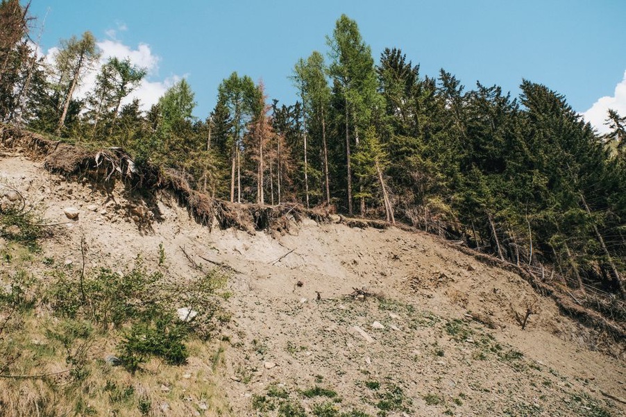
Operations and maintenance preserve the original safety margin
Landslide mitigation does not end with construction. Ditches accumulate sediment, culvert inlets become obstructed, vegetation changes, animal burrows create leakage paths, and storm events reshape catchments. Routine inspections should focus on known hazard sites and the drainage features that influence them. Records are most useful when observations can be compared over time and tied to precise locations.
After unusually intense or prolonged rainfall, targeted patrols should inspect crest drains, culvert inlets and outlets, cuttings, retaining systems, debris barriers, and track sections below known slopes. An up-to-date inventory of hazard locations, previous incidents, investigation data, drainage assets, and installed instruments helps operators prioritise resources and identify recurring patterns.
Railway landslide resilience also intersects with wider corridor hazards. Earthquake-triggered ground movement can damage earthworks and structures at the same time; the principles discussed in seismic resilience in highway design and corridor function after earthquakes provide useful context for network-level emergency planning, while railway-specific ground and track behaviour still requires its own assessment.
Common weaknesses in risk management
- Treating drainage as secondary work: blocked or incomplete drainage can defeat otherwise effective slope measures.
- Using generic stability assumptions: local weak layers, groundwater pressures, and old slide deposits can govern behaviour.
- Ignoring construction sequence: temporary works may create the highest-risk configuration.
- Equating absence of movement with safety: a dry-season inspection may not represent wet-season conditions.
- Installing instruments without a response plan: data that are not reviewed and acted upon do not reduce risk.
- Focusing only on the visible slope: upstream catchments, culvert outlets, foundation soils, and adjacent earthworks may control the mechanism.
For a newly identified wet patch beside a railway formation, the first defensible step is to record its exact location, extent, weather context, nearby drainage assets, and any associated track or slope changes. Inspection can then establish whether the source is surface runoff, a failed drain, groundwater seepage, or leakage from an adjacent utility before remedial work is selected.

