When a road fails early, the asphalt surface rarely tells the whole story. Dig into the forensic record and you will find that traffic loading is often a secondary actor. The real trigger sits deeper, in the subgrade and unbound granular layers, where pore water pressure has climbed beyond what the drainage system can handle. Once groundwater enters the structural section, effective stress—the grain-to-grain contact that gives a pavement its bearing capacity—collapses. A base course that tested at a California Bearing Ratio of 80 percent under optimum moisture can slump below 15 percent CBR when saturated. Standard empirical catalogues tend to paper over this drop with a single conservative drainage coefficient, but the numbers leave little room for argument: moisture state dictates strength.
Cyclic traffic loads make the problem worse. Repeated heavy vehicle passes push pore pressure up in saturated fine-grained soils, and that pressure dissipates slowly. Within a single wet season, a stable platform can degrade into a pumping failure. Fines eject through cracks and joints, and the bound layers above lose their structural support piece by piece.
Hydraulic Regimes and Failure Mechanisms
Groundwater does not attack a pavement uniformly. Its impact depends on where the water table sits relative to the formation and how the capillary fringe behaves. A perched water table trapped above an impermeable lens acts differently from a regional aquifer that rises and falls with the seasons. For road engineers, the critical zone is the upper capillary fringe. Here, negative pore pressures—matric suction—lend apparent cohesion to partially saturated soils. When wetting strips that suction away, volume-change failures kick off in expansive clays, and metastable loess deposits undergo collapse settlement.
Failure mechanisms tied directly to groundwater break down into four main patterns:
- Subgrade softening and rutting: Saturation drives down the resilient modulus of the subgrade. Vertical compressive strains concentrate under the wheel paths, and plastic deformation accumulates with each pass.
- Stripping and moisture damage in bound layers: Vapor diffusion and capillary rise carry water to the underside of asphalt layers. Traffic-induced pore pressure then promotes adhesive failure between bitumen and aggregate.
- Slope instability in side-long ground: Elevated groundwater pressure cuts the effective normal stress on potential slip surfaces beneath embankments, shrinking the factor of safety against deep-seated rotational failure.
- Frost heave and thaw weakening: In cold regions, a high water table feeds the moisture migration that builds ice lenses. Spring thaw traps meltwater that cannot drain, leaving the top of the subgrade in a near-zero-strength condition.
Each mechanism runs on its own clock. Pore-pressure spikes happen under individual axle passes. Seasonal degradation cycles accumulate damage over decades. A serious assessment program has to capture both the spatial distribution of saturation and how it shifts over time.
Site Investigation and Instrumentation Strategy
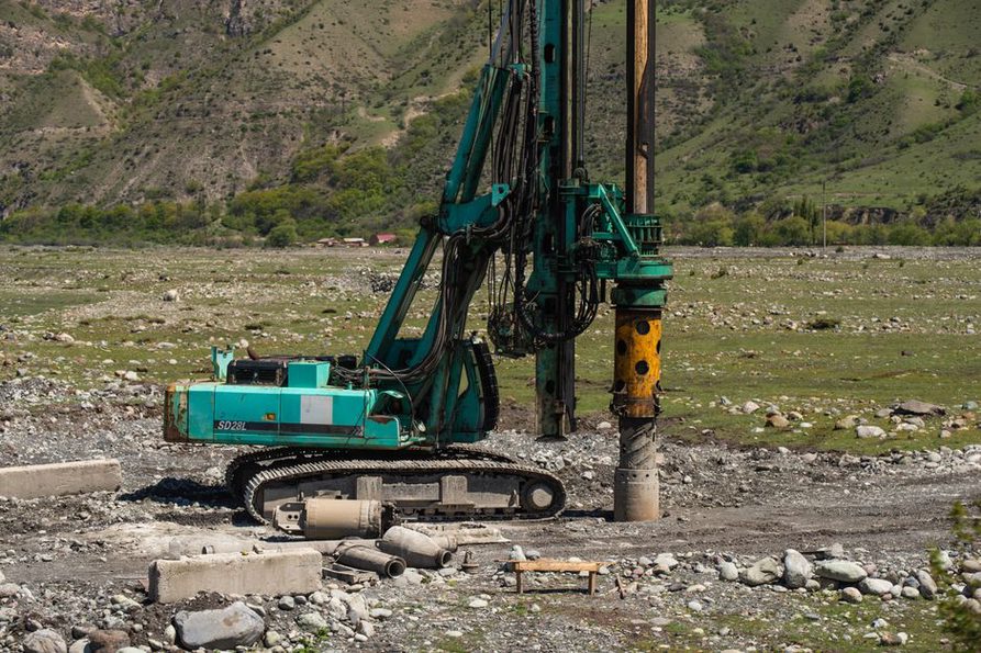
Geological maps and well logs offer a starting point during the desk-study phase, but fluvial and glacial deposits are too heterogeneous to rely on paper alone. Direct subsurface investigation is non-negotiable. Piezocone testing—cone penetration with pore pressure measurement, or CPTu—delivers near-continuous profiles of soil type, relative density, and equilibrium pore pressure. When penetration pauses for a dissipation test, the decay of excess pore pressure is recorded. That decay curve yields an in-situ estimate of the coefficient of consolidation, the parameter that governs how fast the subgrade drains under load.
Long-term monitoring calls for piezometers installed at multiple depths in a single borehole, mapping the seasonal envelope of water table fluctuation. Standpipe piezometers work, but their response lags in low-permeability soils. Vibrating wire piezometers, grouted in with a low-permeability bentonite-cement mix, give a much faster signal. They become essential when the goal is to correlate pore pressure response with individual storm events or tidal cycles. In the upper 1.5 meters of the formation, time-domain reflectometry sensors and capacitance probes track continuous volumetric water content profiles, catching the advance of the wetting front before the groundwater table itself rises.
Instrument data turn actionable when they are linked to a defined threshold. For a silty sand subgrade, a pore pressure ratio exceeding 0.5 during a design storm might trigger a contingency plan for edge drain flushing. For a plastic clay, the critical metric may be the cumulative time that suction stays below 10 kPa—a signal that strength loss is beginning.
Integrating Water into Structural Evaluation
Falling weight deflectometer testing produces deflection basins that moisture state shapes decisively. A backcalculated subgrade modulus is not a fixed material constant. It is a snapshot of stiffness at the moment of testing. To isolate the groundwater effect, schedule deflection campaigns for the worst-case scenario—late winter or early spring, after maximum infiltration—and compare the results against summer baselines. The deflection ratio between the sensor at the load plate center and a sensor at a 900 mm offset helps discriminate whether a weak layer sits deep in the subgrade, exactly where groundwater influence tends to concentrate.
Ground penetrating radar opens a complementary, non-destructive window into moisture distribution inside the pavement structure. Dielectric constant contrasts map zones of free water pooling in granular base layers, especially at the interface with a less permeable subgrade. Calibrated against ground-truth cores, GPR surveys can pinpoint stretches where edge drains have failed and water is ponding within the structural section. This approach belongs to the wider discipline of infrastructure diagnostics: combining surface geophysics with targeted sampling to cut uncertainty in rehabilitation design. Where underground structures intersect the water table, the problem extends into the territory covered by The Complexities of Tunnel Maintenance, where groundwater inflow management is a continuous operational demand rather than a seasonal concern.
Drainage Design as a Structural Element
Treating drainage as a secondary detailing item remains a persistent design error. The hydraulic conductivity of the base course and the geometry of the drainage path together define how long it takes to dissipate moisture from construction and infiltration. This time-to-drain criterion—often specified as the period to drop from full saturation to 50 percent saturation—should directly inform layer thicknesses and filter gradations. High-volume highways typically target drainage within two hours, which demands a base course permeability on the order of 300 meters per day for a standard lane width and cross-slope.
Geotextile separators and filters at the subgrade-base interface block the upward migration of fines while letting water pass. Selecting the apparent opening size and permittivity is a soil-retention and hydraulic-capacity problem that must account for the gradient and the particle-size distribution of the subgrade. Over time, these geotextiles can clog. Biological growth or chemical precipitation—common in groundwater rich in iron or calcium carbonates—cuts transmissivity, a degradation mode invisible from the surface until structural distress appears.
Edge drains, whether prefabricated geocomposite fin drains or conventional French drains with perforated pipe, need a positive outlet. In flat terrain, the outlet elevation may be controlled by the flood level of the receiving water body. A drain submerged during high-water events stops functioning and can turn into a backflow pathway, actively injecting water into the base layer. Hydraulic design must therefore consider the joint probability of the design storm and the receiving stream stage. This coupled analysis is often missing from standard highway drainage manuals.
Groundwater Control in Cut and Fill Sections
Cut sections excavate the roadway below natural ground, intercepting the groundwater flow path. The resulting drawdown toward the road prism can keep a continuous supply of water moving into the subgrade unless it is intercepted first. Cutoff drains, installed parallel to the roadway and keyed into an impermeable stratum, are meant to catch this lateral flow before it reaches the pavement structure. Their depth and spacing come from a flow-net analysis of the hillslope hydrogeology, not from a prescriptive standard detail.
Embankments on soft, saturated foundation soils pose a different challenge. The weight of the fill imposes a surcharge load that generates excess pore pressures in the underlying clay. The rate of consolidation governs time-dependent settlement and the gain in undrained shear strength. Preloading combined with vertical wick drains accelerates the process by shortening the drainage path, but the designer must confirm that the receiving drainage blanket at the base of the embankment has enough discharge capacity to handle the expelled water without backing up. Monitoring this process with settlement plates and piezometers is a core part of the observational method in embankment construction. The interplay between fill placement, pore pressure dissipation, and foundation stability extends directly from the principles discussed in Understanding the Impact of Dynamic Transport Loads on Soil Structures, where long-term performance hinges on the initial consolidation state achieved during construction.
Toward Performance-Based Assessment
Empirical drainage coefficients are convenient for design specification, but they fall short when you need to assess the remaining service life of an existing road where groundwater conditions have shifted. A performance-based evaluation links the measured or modeled degree of saturation to a mechanistic-empirical distress model. For rutting, that means adjusting the local calibration coefficients of the transfer function to reflect the reduced resilient modulus of the unbound layers under elevated moisture. For transverse cracking and faulting in rigid pavements, it means accounting for the loss of subgrade support beneath slab corners, where pumping erosion hits hardest.
The necessary input is a time-series of moisture content or pore pressure at the critical depth—typically the top of the subgrade. When continuous monitoring data are not available, a synthetic moisture history can be built from a water-balance model driven by daily precipitation and potential evapotranspiration, calibrated against the soil-water characteristic curve of the subgrade material. The output is a probabilistic distribution of the resilient modulus over the design life. That distribution feeds directly into a reliability-based prediction of distress initiation and progression. Instead of a single deterministic CBR value, the assessment yields a risk-informed engineering judgment that reflects the real variability the subsurface water regime imposes.