Tunnel alignments can pass through ground that appears uniform yet changes sharply in stiffness, groundwater pressure, permeability, or stress state within a few metres. This is a defining challenge of underground transport work: the ground is both the construction medium and a load-bearing system, and it cannot be fully observed before excavation.
Metro tunnels, underground stations, rail caverns, road tunnels, pedestrian connections, and utility interfaces must perform safely during construction and throughout decades of operation. Excavation redistributes stress, groundwater responds to new drainage paths, support stiffness influences deformation, and movement at depth can affect buildings, tracks, roads, pipelines, and retaining structures at the surface.
Ground uncertainty is a primary design condition
Ground investigation is more than an initial data-collection exercise. It underpins excavation-method selection, estimates of support demand, monitoring plans, and construction-risk allocation. Boreholes, trial pits, geophysical surveys, laboratory and in-situ testing, groundwater measurements, existing records, and inspections of nearby structures each contribute to the geological model.
No investigation removes uncertainty entirely. Boreholes provide discrete observations within a three-dimensional ground mass, and significant variability may lie between them. The aim is a ground model that identifies credible strata, faults, weak zones, permeable horizons, made ground, cavities, aggressive groundwater, and the range of engineering parameters likely to govern performance.
Why geological boundaries matter
The most difficult conditions often occur at transitions rather than within one named soil or rock type. A tunnel may pass from competent rock into weathered or fractured rock, soft clay, loose saturated sand, or ground affected by historic workings. Such changes can alter face stability, cutting-tool wear, water inflow, settlement behaviour, and the support measures required with little warning.
Urban ground can be particularly complex. Former basements, abandoned foundations, buried channels, poorly documented utilities, backfilled excavations, and historic industrial uses may create local anomalies that do not appear on a regional geological map. Design teams need to reconcile historic records with current investigation data rather than treating either source as complete.
Excavation changes the stress and water regime
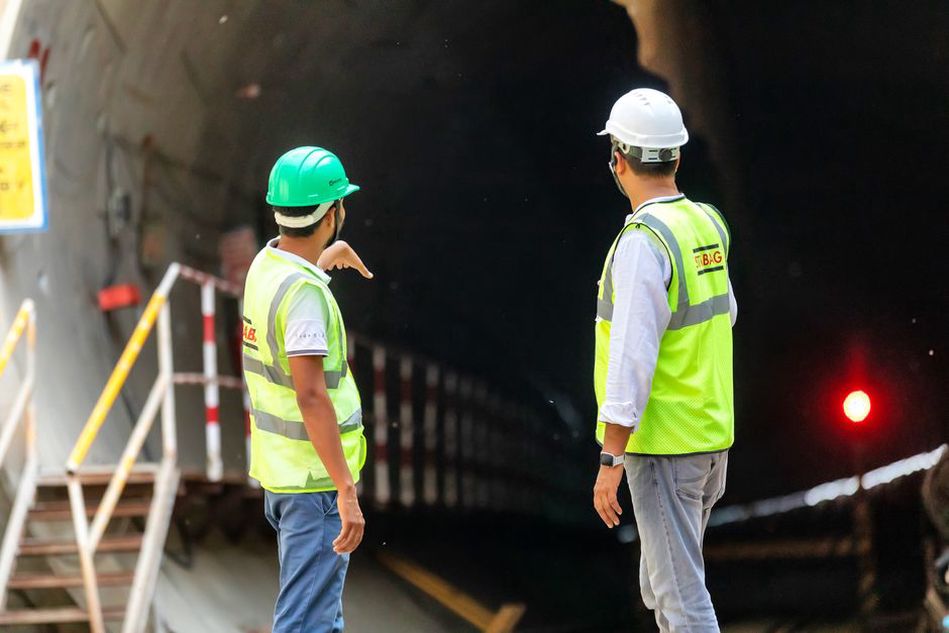
Before excavation, soil and rock carry in-situ stresses related to self-weight, tectonic history, groundwater pressure, and restraint from surrounding strata. Removing material redistributes those stresses around the opening. Ground may move towards the excavation, a supported face may deform, and temporary support or the permanent lining must carry loads that change as work advances.
In many materials, this response is time-dependent. Soft clays may consolidate as pore pressures change. Squeezing ground can continue to converge after support installation. Some rocks degrade when exposed to water or stress relief. Stiff ground masses, meanwhile, can transmit excavation-induced movements farther than expected where joints, bedding, or other discontinuities control their behaviour.
Face stability and volume loss
For bored tunnels in soft ground and below the water table, controlled pressure at the excavation face is critical. Too little support pressure can lead to ground loss, inflow, and settlement. Too much can heave the ground or disturb nearby assets. The acceptable operating range depends on local soil conditions, groundwater pressure, cover depth, adjacent foundations, and the excavation system.
For mined or sequentially excavated tunnels, stability depends on excavation sequence, advance length, ground reinforcement, immediate support, and interaction between headings, cross-passages, shafts, and station enlargements. An approach suitable for a small running tunnel may not suit a wide platform cavern, where span, geometry, and staging create a different stress field.
Surface settlement is often linked to volume loss into an excavation, but it should not be treated as one predictable value. The settlement trough and its effects depend on depth, ground type, construction control, existing foundations, and the way movements accumulate from adjacent excavations. This is particularly important in urban corridors beneath sensitive surface infrastructure; settlement monitoring for urban transport infrastructure explains how movement data can support staged decision-making.
Groundwater must be treated as a structural and environmental issue
Water affects excavation stability, lining loads, durability, construction logistics, and the surrounding environment. A tunnel below the water table may be subject to hydrostatic pressure throughout its service life. Joints, penetrations, segmental interfaces, construction defects, drainage details, and changes in groundwater chemistry all affect the likelihood and consequences of leakage.
Temporary drawdown can reduce water pressures locally, yet it may also cause consolidation settlement in compressible deposits, reduce flows to water-dependent features, or mobilise fines in susceptible soils. In permeable ground, uncontrolled inflow can carry sand or silt into the excavation, leaving voids that contribute to surface settlement. In fractured rock, water pathways may be highly variable and need not align neatly with mapped lithological units.
Waterproofing and drainage concepts need to suit the expected pressure regime and the operator's maintenance capability. Drained systems require dependable collection, pumping, access, and long-term inspection. Undrained or pressure-resisting systems rely heavily on sound joints, membranes, penetrations, and quality assurance. Neither approach is universally preferable; the choice depends on hydrogeology, operational constraints, environmental permissions, and the consequence of failure.
Risks are often greatest at portals, shafts, and shallow cut-and-cover sections, where surface runoff, utility corridors, and variable fill can concentrate water. Principles used for road drainage and pavement performance remain relevant at these interfaces: water paths need to be understood, kept clear, inspected, and connected to a system able to manage design flows safely.
Underground stations are often harder than running tunnels
Running tunnels are usually repetitive in section and excavation sequence. Stations, crossover caverns, ventilation adits, emergency egress routes, and underground interchanges interrupt that regularity. They involve larger spans, deeper excavations, multiple interfaces, and more complicated structural arrangements.
Deep station boxes may require retaining systems that restrict deformation near neighbouring structures and utilities. Construction can involve temporary slabs, internal bracing, anchors, diaphragm walls, groundwater cut-offs, and staged excavation. The completed station must then resist earth and water pressures while accommodating openings for platforms, concourses, escalators, ventilation, cable routes, and fire-separated spaces.
Interfaces drive disproportionate risk
Defects and delays often arise at interfaces rather than within standard tunnel rings or station walls. Typical examples include:
- connections between a bored tunnel and a cut-and-cover structure;
- waterproofing transitions at joints, cross-passages, and penetrations;
- changes from flexible temporary support to stiff permanent works;
- clearance conflicts between structural members, mechanical systems, and evacuation routes;
- protection or diversion of utilities crossing above or beside excavations;
- interfaces between new works and retained historic structures.
These locations merit focused constructability reviews and explicit inspection hold points. Drawings rarely reveal every tolerance or access issue. Three-dimensional coordination, mock-ups for repeated details, and contractor input during design development can identify conflicts before they require changes underground.
Fire, life safety, and ventilation shape the civil design
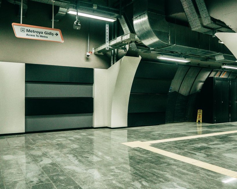
Underground transport systems have constrained escape routes and limited means of dispersing smoke. Civil, mechanical, electrical, signalling, and operational teams therefore need an agreed safety strategy early enough to influence geometry. Tunnel cross-section, passage spacing, station layout, shaft location, fire compartmentation, smoke extraction, emergency lighting, communications, and responder access are interdependent.
Ventilation infrastructure can impose major space and construction demands. Fans, dampers, ducts, shafts, intake and exhaust structures, plant rooms, noise-control measures, and maintenance clearances may compete with structural members and passenger circulation. A shaft that works well aerodynamically may still be difficult to build because of utilities, constrained property boundaries, archaeological sensitivity, or weak ground.
Operational scenarios matter as much as nominal capacity. Designers assess routine ventilation and thermal loads alongside stalled trains, emergency evacuation, smoke movement, power loss, and the ability to isolate parts of the system. Requirements vary by jurisdiction and project type, so assessments should be developed against applicable regulations, operator procedures, and independently reviewed safety analyses rather than copied from unrelated schemes.
Public reporting on major tunnel incidents, including the BBC's coverage of the Mont Blanc tunnel fire and its safety legacy, shows why emergency systems must be considered alongside infrastructure geometry, operations, and maintenance.
Durability begins with exposure classification and detailing
Concrete linings, reinforcement, steel elements, waterproofing, cable supports, drainage components, track slabs, and fixings may be exposed to moisture, chlorides, sulfates, stray current, cleaning chemicals, diesel contaminants, and cyclic thermal conditions. The service environment can vary sharply across one asset: a dry running tunnel, damp portal, station washdown area, and sump may each impose different exposure conditions.
Durable performance depends on more than material selection. Crack control, cover, joint detailing, workmanship, curing, material interfaces, leak management, and inspection access all matter. For precast segmental linings, dimensional tolerances and gasket installation affect ring geometry as well as watertightness. For cast in-situ structures, concrete placement sequence, construction joints, and curing conditions can determine whether a nominally sound specification achieves its intended resistance.
Stray current and railway-specific effects
Electrified rail systems can create stray-current corrosion risks where return currents leave their intended route and enter buried metallic infrastructure. Mitigation requires coordinated track insulation, bonding, electrical monitoring, drainage, structural reinforcement arrangements, and interfaces with third-party utilities. It needs to be addressed early, because later changes can be difficult once track and finishes are installed.
Trackform also affects maintenance and vibration transmission. Ballasted track allows adjustment but requires access for tamping and renewal. Slab track can provide stable geometry with less routine intervention, but it demands careful construction tolerances, resilient elements where required, and realistic repair strategies. The appropriate choice depends on alignment, operational loading, vibration criteria, drainage, access windows, and whole-life maintenance planning.
Construction logistics can control technical feasibility
Access shafts and portals are more than entry points. Their size, location, lifting capacity, spoil-handling arrangements, ventilation, emergency access, and neighbourhood constraints affect the achievable construction programme. A long tunnel with few shafts may offer limited opportunities to remove spoil, deliver segments and support materials, install systems, or respond to an incident.
Material handling is especially demanding in dense urban areas. Tunnel boring machines need assembly, launch, reception, maintenance, and eventual removal or abandonment plans. Mined construction depends on dependable delivery of support materials and removal of spoil. Logistics planning must also address dust, noise, vibration, traffic movements, working hours, and public safety around surface sites.
| Design issue | Potential consequence | Useful control approach |
|---|---|---|
| Variable ground and hidden obstructions | Face instability, damage, delay | Progressive ground model, probe investigations, observational controls |
| Groundwater inflow | Settlement, flooding, lining leakage | Hydrogeological testing, pressure management, verified waterproofing details |
| Adjacent assets | Service interruption or structural distress | Condition surveys, movement criteria, real-time monitoring and response plans |
| Confined systems space | Installation conflicts and poor maintainability | Multidisciplinary spatial coordination and access reviews |
| Limited shaft access | Programme and emergency-response constraints | Construction logistics modelling and staged access planning |
Monitoring is a management system, not an instrument list
Instrumentation may include settlement points, inclinometers, extensometers, piezometers, load cells, strain gauges, track-geometry measurements, vibration sensors, and automated total-station targets. Its value depends on connection to a defined decision process. A reading without a baseline, alert threshold, trend interpretation, responsible owner, and response action provides limited protection.
The observational method works only when its prerequisites are in place: foreseeable behaviour has been identified, monitoring can detect divergence early enough, practical corrective measures are available, and authority to stop or alter work is clear. Data must also be checked against instrument error, construction events, rainfall, temperature effects, and other possible causes before it is interpreted as structural movement.
Monitoring may need to continue into operation where long-term mechanisms remain plausible, including consolidation settlement, groundwater recovery, leakage, corrosion, track movement, or joint deterioration. Handover information should retain baseline records, as-built geometry, instrument locations, inspection history, and the assumptions used to establish operational limits.
Design for maintainability and recovery
Underground assets are costly to access after commissioning. A small component failure may require night possessions, electrical isolation, confined-space procedures, passenger disruption, and specialist lifting arrangements. Design reviews should test whether drainage channels can be cleared, pumps replaced, dampers inspected, cable routes accessed, leakage traced, and critical equipment isolated without disproportionate disruption.
Resilience also concerns recovery after abnormal events. Flooding, fire, derailment, power loss, local lining damage, and equipment failure may not be fully preventable. Compartmentation, drainage capacity, redundant routes, protected communications, and safe access can reduce restoration time. This is particularly important at network bottlenecks, where closure of one interchange or river crossing can affect a large part of the service.
A useful final review is to follow one water-leak scenario through an actual station or tunnel chain: where is water detected, which sump receives it, how does the alarm reach control staff, how is the affected area accessed, where can a replacement pump be brought in, and does that route remain available during passenger operation? The resulting gaps often lie at penetrations, access hatches, power-isolation points, and drainage interfaces rather than in the main structural concept.