Seismic loading affects tunnels differently. A shallow cut-and-cover structure beneath soft urban deposits may be governed by soil deformation and joint distress. A deep rock tunnel may instead be most vulnerable at portals, faults, cavern intersections, or transitions between weak and stiff ground. Assuming that an underground structure is uniformly protected can obscure the locations where earthquake damage is most likely to begin.
Seismic risk evaluation brings together regional hazard, local ground response, geological structure, groundwater conditions, tunnel configuration, and the operational consequences of damage. The purpose is not simply to calculate a design acceleration. It is to identify credible earthquake-induced deformation mechanisms, estimate their effects on the lining and associated systems, and confirm that design assumptions remain valid through construction and operation.
Start with the hazard that can produce deformation
Regional seismic hazard provides the initial loading basis, commonly expressed through response spectra, peak ground acceleration, duration, and, in some studies, time histories compatible with site conditions. These parameters are necessary, but they do not define tunnel demand by themselves. Underground structures generally respond to differential movement in the surrounding ground rather than inertia in the way an elevated bridge pier or building frame does.
A useful assessment separates two related questions:
- What shaking is plausible at the site? This includes earthquake source characterization, magnitude, distance, fault mechanism, and the probability level required by the governing project criteria.
- How will the ground deform? This depends on stratigraphy, stiffness contrasts, topography, basin effects, pore-water pressures, discontinuities, and permanent ground-displacement hazards.
Both probabilistic seismic hazard analysis and scenario-based deterministic assessment can be useful. Probabilistic analysis helps define shaking levels associated with selected exceedance probabilities. Deterministic scenarios are particularly informative where a nearby active fault, a known liquefiable deposit, an unstable slope, or a fault-crossing corridor may govern the design. The chosen approach and performance targets should comply with applicable regulations and be reviewed by qualified seismic and geotechnical specialists.
Build a ground model suitable for dynamic behavior
A geotechnical model adequate for excavation support may not be adequate for seismic analysis. The seismic model must represent the soil and rock properties that control wave propagation and cyclic deformation, including unit weight, shear-wave velocity, small-strain shear modulus, strain-dependent modulus reduction, damping behavior, cyclic strength, permeability, and groundwater conditions.
Ground investigation priorities
Investigation planning should address variability, not just average conditions. Boreholes, geological mapping, geophysics, laboratory testing, in-situ testing, and groundwater observations should be interpreted together. Key issues include:
- soft or loose alluvial layers over stiffer material;
- filled ground and reclaimed land near portal areas or stations;
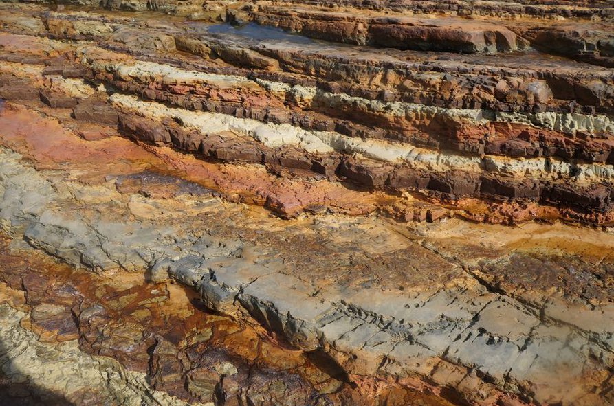
- weathered rock zones, shear zones, and major discontinuities;
- abrupt changes in overburden thickness or tunnel depth;
- groundwater levels and their seasonal or construction-related variation;
- soil types susceptible to liquefaction, cyclic softening, or excessive settlement.
Shear-wave velocity profiling is often central to site-response work because it characterizes the stiffness that controls seismic-wave travel and amplification. One profile should not, however, be assumed representative of a long alignment without supporting evidence. Tunnels often cross several geological units, each of which may require a separate ground model or a carefully justified zoning approach.
Identify the tunnel-specific earthquake mechanisms
Ground shaking can cause racking, ovaling, axial strain, bending, shear, joint opening, and local lining distortion. The governing mechanism depends on tunnel shape, depth, lining stiffness, soil stiffness, and the interface behavior between the ground and the support system.
| Mechanism | Typical setting | Potential consequence |
|---|---|---|
| Transverse racking or ovaling | Shallow tunnels in deformable soil | Lining bending, wall-to-roof joint distress, cracking |
| Longitudinal deformation | Long alignments crossing variable ground | Axial force, curvature, segment-joint movement |
| Liquefaction and lateral spreading | Loose saturated granular deposits | Settlement, flotation, distortion, portal movement |
| Fault displacement | Alignment crossing or near an active fault trace | Highly localized permanent distortion or rupture demand |
| Slope failure and rockfall | Portals in steep or fractured terrain | Blocked access, structural damage, drainage disruption |
| Interface movement | Transitions to stations, shafts, cut-and-cover sections | Concentrated strain at stiffness changes |
Permanent ground deformation requires separate consideration from transient shaking. A tunnel may tolerate a calculated level of cyclic racking yet remain vulnerable to differential settlement, lateral spreading, or tectonic offset imposed over a short distance. At a fault crossing, the key inputs are often the expected displacement pattern, the width of the deformation zone, its direction relative to the alignment, and uncertainty in the fault location—not peak acceleration alone.
Account for tunnel form, supports, and interfaces
Circular bored tunnels generally distribute radial ground pressure efficiently, but segmental joints, gasketed interfaces, and cross-passage connections can be sensitive to relative movement. Rectangular cut-and-cover tunnels may be more vulnerable to racking because walls and slabs respond differently to distortion in the surrounding soil. NATM or sequentially excavated tunnels require attention to the interaction among primary support, final lining, rock mass, and construction joints.
Stiffness discontinuities are recurrent weak points. They include transitions from bored tunnel to station box, tunnel to portal structure, soil to rock, and one lining type to another. Where adjacent elements move differently during seismic deformation, demands may concentrate at connectors, joints, waterproofing details, and utility penetrations. Analytical models should represent these transitions explicitly when they are material to performance.
The assumed lining-ground interaction also matters. Treating the interface as either perfectly bonded or fully slipping without justification can distort results. Interface conditions depend on construction method, contact grouting, annular gaps, drainage arrangements, ground type, and expected strain level. Sensitivity studies can show whether these assumptions materially affect predicted demand.
Use analysis methods in proportion to the risk
Screening-level evaluations may use simplified deformation-based methods to estimate lining forces from free-field ground strains. These methods are efficient and transparent for regular tunnel sections in relatively uniform ground. Their limitations become important where geometry is complex, soil behavior is strongly nonlinear, liquefaction is possible, or permanent displacement governs.
More detailed work may include one-dimensional site-response analysis, two-dimensional soil-structure interaction models, and three-dimensional numerical models. Greater model complexity should answer a defined engineering question, such as the effect of a station interface, nonuniform overburden, fault displacement, or a cross-passage arrangement. A sophisticated model based on poorly constrained material properties does not necessarily lead to a more reliable decision.
Model verification should cover geometry, boundary conditions, mesh adequacy, compatibility of input motions, damping treatment, constitutive-model limitations, and the plausibility of predicted deformations. Where possible, results should be checked against simplified calculations. Large discrepancies may reflect a genuine interaction, but they can also reveal an input or modelling error.
Translate structural response into operational performance
Life safety is essential, but it is not the only performance target for a transport tunnel. The owner may require controlled damage, rapid inspection, emergency access, limited water ingress, continued use by emergency vehicles, or a defined recovery period for rail or road operations. Those objectives determine which components require assessment.
Beyond the primary lining, the review should consider:
- waterproofing membranes, gaskets, and drainage paths;
- track slabs, ballastless track systems, road pavement, and invert drainage;
- ventilation, lighting, power supply, communications, and fire-life-safety equipment;
- shafts, portals, retaining walls, emergency exits, and cross-passages;
- connections to stations, bridges, depots, and surface transport networks.
A tunnel can remain structurally stable yet be unavailable if settlement disrupts track geometry, damaged joints admit water, or electrical and ventilation systems lose function. Performance criteria therefore need measurable indicators, such as allowable deformation, applicable crack-width ranges, watertightness expectations, preserved clearances, and inspection triggers. These criteria must be project-specific and established under the applicable design framework.
Manage uncertainty through construction and operation
Seismic risk does not become fixed when design drawings are issued. Excavation can expose faulted zones, altered rock, unexpected fill, or groundwater conditions that change the original assessment. An observational approach links investigation findings, design assumptions, monitoring, and predefined responses. Instrumentation should follow the governing risk mechanism: settlement points and inclinometers for lateral ground movement, piezometers for pore pressure, convergence monitoring for excavated tunnels, and structural sensors where joint movement or lining strain is a concern.
In urban projects, construction-induced ground movement can complicate subsequent interpretation of seismic vulnerability. The related issues of baselines, thresholds, and response planning are addressed in Managing Ground Movement and Risk in Urban Tunnel Excavation. Baseline surveys, as-built records, and documented changes in ground conditions provide essential reference data after an earthquake.
Prepare an inspection and recovery basis before an earthquake
Post-event decisions are faster and easier to defend when inspection routes, access requirements, damage categories, and escalation criteria are set in advance. Initial inspections commonly focus on portals, fault or weak-ground zones, interfaces, joints, water-ingress locations, track or pavement alignment, overhead systems, ventilation equipment, and emergency egress. Remote sensing and automated diagnostics can support initial screening, but they do not replace targeted engineering inspection where deformation or loss of support is suspected.
More detailed methods for combining condition data with tunnel safety decisions are discussed in Enhancing Tunnel Safety with Advanced Diagnostics. For a practical recovery plan, each high-risk chainage should have a record of the expected damage mechanism, accessible inspection points, relevant instruments, acceptable operating restrictions, and the specialist review required before normal service resumes.