Water often turns a marginally stable transport cut or embankment into an operational failure. A brief period of intense rainfall can raise pore-water pressures, soften susceptible soils, erode a ditch outlet, or overload a drainage layer. The visible result may be a shallow slip beside a road or track, while the controlling mechanism extends well below the surface and beyond the damaged area.
Stabilizing slopes for highways, railways, approach roads, and tunnel portal areas is not a matter of selecting a single product. It requires a coordinated response to ground conditions, geometry, groundwater, construction sequence, loading, and the consequences of movement. The objective is adequate stability under credible short- and long-term conditions, with deformation, erosion, and maintenance kept within acceptable limits.
Start with the failure mechanism, not the treatment
A slope may fail through shallow erosion and raveling, rotational sliding in cohesive soil, translational sliding along a weak layer, rock wedge or planar failure, debris flow, or progressive deformation beneath an embankment. Each mechanism calls for a different response. Erosion-control matting applied to a deep rotational failure, for instance, may improve the surface appearance while contributing little resistance to the sliding mass.
The investigation should establish the geometry and materials of the slope and its foundation. This includes the depth and condition of weathered zones, rock discontinuities, fills, weak seams, groundwater levels, seepage routes, and evidence of historic movement. Useful evidence can include boreholes, safely excavated trial pits, laboratory testing, geophysical surveys interpreted alongside intrusive data, terrain models, drainage records, and mapping of scarps, tension cracks, tilted vegetation, wet ground, and blocked culverts.
Designers also need a clear understanding of loading and consequences. Railway slopes may be affected by repeated dynamic loading and tight track-alignment tolerances. Road cuts can be constrained by widening works, traffic beneath the slope, and runoff concentrated by pavement drainage. Near bridges and retaining approaches, changes in embankment loading, abutment movement, and drainage interfaces may govern performance.
Conditions that must be checked
- Temporary construction stages: Excavation, fill placement, dewatering, and delayed installation of permanent support may create the critical condition.
- Water scenarios: Seasonal groundwater, prolonged rainfall, rapid drawdown, flood surcharge, and blocked drainage outlets can produce very different pore-pressure conditions.
- Material variability: Thin clay seams, loose fill lenses, colluvium, and weathered rock contacts may control the slip surface even when they appear minor in a generalized ground model.
- Long-term change: Vegetation loss, drainage deterioration, adjacent development, climate-driven rainfall extremes, and erosion can reduce available stability over time.
- Infrastructure tolerance: Movement tolerable beside a low-volume access road may be unacceptable near a high-speed railway or tunnel portal.
Formal slope-stability analyses should reflect the identified mechanism and uncertainty in ground parameters. Limit-equilibrium methods, numerical modelling, rock-slope kinematic assessment, and observational approaches all have a place. Their output is only as credible as the ground model and water assumptions behind it.
Drainage: reducing the driving force
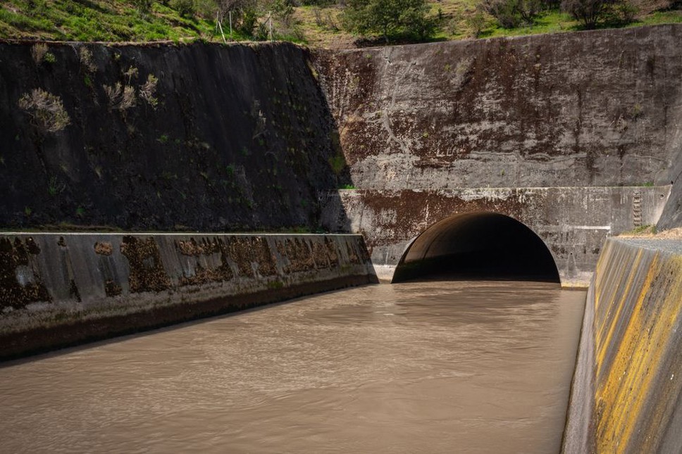
Drainage is often the most effective stabilization measure because it limits water entering the slope and reduces pore-water pressure within it. It must be designed as a system: collection, conveyance, discharge, inspection access, and maintenance all matter. A drain that collects water and releases it onto an unprotected lower slope may simply move the problem downhill.
Surface-water control
Catch drains above a cut slope intercept runoff before it reaches the crest. Berm drains, lined channels, curb outlets, downchutes, and energy dissipators direct water safely across or around the face. Outlets deserve particular attention because concentrated flow can scour soil, undermine toe protection, and form gullies that progressively steepen the slope.
Grading should prevent ponding near crests, uncontrolled discharge from pavement gullies, and depressions that direct runoff into tension cracks. Where erosion risk is significant, vegetation, erosion-control blankets, turf reinforcement, rock protection, articulated systems, or other surface measures may be selected to suit hydraulic loading and soil conditions. These measures limit soil detachment and rilling; they do not replace deep stabilization where internal sliding is the concern.
Subsurface drainage
Horizontal drains, trench drains, drainage blankets, filter layers, toe drains, and drainage galleries can intercept or relieve groundwater, depending on geology and access. Filter compatibility is essential. A poorly selected filter may clog, permit fine-particle migration, or contribute to internal erosion. Outlets must remain open and accessible for inspection.
Drainage also needs to be coordinated with pavement, track, and structure drainage. The link to service life is direct: poor water management weakens both supporting ground and pavement layers. Guidance on extending pavement service life through drainage, construction control, and targeted maintenance is particularly relevant where road runoff discharges near embankment slopes.
Geometry modification and toe support
Flattening a slope reduces driving forces and can provide a durable, low-maintenance solution where land is available. Benching long faces can interrupt runoff, provide construction access, and assist drainage, but benches must drain positively and must not become water traps. Removing unstable material from the crest or upper slope can also reduce loading on a potential slip surface.
At the lower slope, a buttress fill, rockfill berm, shear key, or engineered toe support can increase resistance to movement. The selected fill needs suitable strength, drainage characteristics, placement control, and foundation preparation. A toe berm placed on soft, saturated ground may settle, spread, or move laterally, with little net benefit unless the foundation is addressed.
For embankments, staged construction and temporary surcharge may be used to manage foundation consolidation and strength gain where appropriate. Instrumentation is particularly important when the design relies on observed settlement and pore-pressure dissipation. Construction should not proceed merely because a planned date has arrived; the next stage should follow agreed monitoring criteria and field observations.
Reinforced-soil systems
Reinforced soil combines compacted fill with tensile inclusions such as geogrids, geotextiles, steel strips, or other reinforcement systems. It can create steepened slopes, widen embankments, support approach fills, and reduce the footprint compared with a flatter unreinforced slope. Performance depends on reinforcement length, connection and facing details where used, fill quality, compaction, drainage, global stability, and interaction with the founding soil.
Geosynthetics may also provide separation, filtration, drainage, or erosion-control functions, which are distinct from primary reinforcement. Selection should consider installation damage, creep, chemical and biological exposure, interface friction, survivability during compaction, and long-term design conditions. The practical differences between these functions are detailed in Geosynthetics in Road Construction: Functions, Selection, and Installation.
Reinforced slopes should not be considered self-contained structures. External stability, bearing capacity, settlement, global slip surfaces passing behind or beneath the reinforced zone, and water flow at the crest and toe remain critical checks.
Structural restraint for constrained corridors
Where slope flattening is not possible or the consequences of movement are severe, structural measures may be required. Common options include retaining walls, anchored walls, soil nail walls, bored or driven pile rows, secant-pile systems, micropiles, ground anchors, and reinforced concrete facing systems. Suitability depends on ground type, groundwater, available working space, utilities, vibration restrictions, drilling access, and the expected depth of movement.
Soil nails and anchors
Soil nailing generally reinforces a mass of ground using closely spaced passive inclusions installed as excavation advances downward in lifts. It is best suited to conditions where the soil can stand temporarily between excavation stages and where drilling and grouting can be controlled. Facing, drainage, corrosion protection, nail pullout resistance, and global stability require integrated design.
Ground anchors provide active restraint through a bonded length in competent ground and a free length that transfers load to the facing or wall. They can be effective where movement must be limited, but require rigorous testing, lock-off control, corrosion protection, and provision for inspection or monitoring. Anchor zones must not conflict with property boundaries, buried services, future excavations, or other infrastructure.
Piles, walls, and shear-transfer elements
Pile rows and embedded walls can intercept a sliding mass or retain a cut where a stable founding stratum is available at depth. Their performance is governed by lateral soil response, bending and shear demand, pile spacing, head restraint, groundwater effects, and the possibility of a slip surface bypassing the system. A wall also requires effective drainage: hydrostatic pressure can become a governing load when drainage paths fail.
Rock slopes require discontinuity-based design
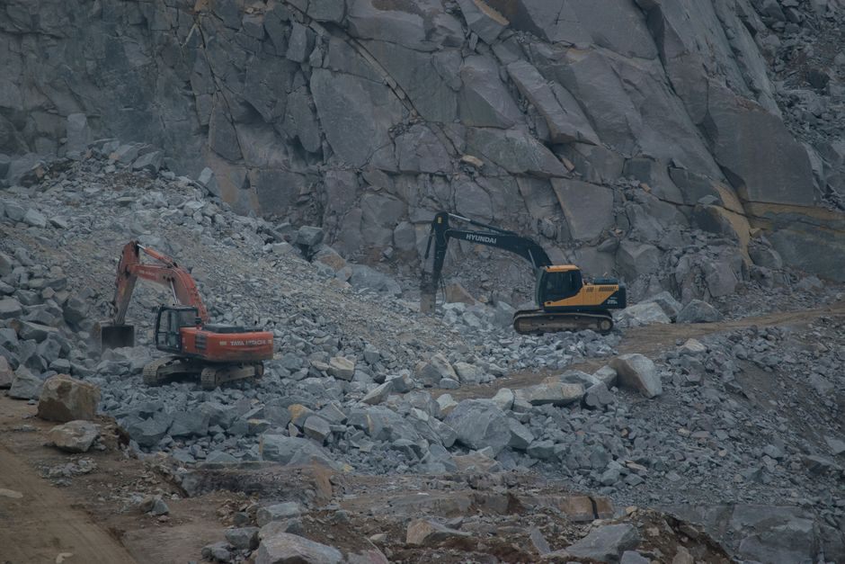
Rock-cut hazards are controlled less by average intact-rock strength than by joints, bedding, faults, weathering, groundwater, block size, and slope orientation. Mapping discontinuities and comparing their orientation with the excavated face helps identify whether planar sliding, wedge sliding, toppling, or rockfall is plausible. Scaling, controlled blasting, reprofiling, rock bolts, dowels, anchors, mesh, draped netting, shotcrete, and catch ditches may be combined according to the hazard.
Rockfall protection and rock-slope stabilization are not interchangeable. Mesh may retain small fragments, while larger blocks may require anchoring, barriers, catch fences, ditches, or changes to the exposed slope geometry. The design must also account for the runout path and the clearance envelope of the road or railway below. Public reporting on major landslides, such as BBC coverage of the Colombia landslide, illustrates how quickly slope failures can disrupt transport routes and isolate communities; site-specific engineering still depends on local ground data, not conclusions drawn from headlines.
Construction quality and monitoring determine whether the design works
Field control is central to stabilization performance. Excavation may reveal weaker material, springs, open joints, or fill boundaries that were not resolved during investigation. The design team needs a defined process for recording these observations, reassessing the ground model, and modifying the works when trigger conditions are met.
Typical monitoring may include survey prisms, inclinometers, piezometers, settlement plates, crack gauges, anchor load cells, and remote sensing used as a screening tool. Instrument selection should follow the predicted movement. Inclinometers help identify the depth and rate of shear displacement; piezometers indicate water-pressure trends; survey points show surface movement but do not directly define the slip plane. Readings need baseline data, inspection intervals suited to construction risk, threshold values, and a response plan that assigns authority to stop work.
| Observed condition | Likely concern | Immediate engineering response |
|---|---|---|
| New tension cracks near crest | Developing deformation or loss of support | Restrict access, inspect drainage, survey movement, reassess stability |
| Persistent seepage or turbid discharge | Elevated pore pressure or internal erosion | Trace flow path, clear outlets, inspect filters and collect water-level data |
| Bulging at toe | Potential rotational or translational movement | Survey urgently, avoid toe excavation, review need for unloading or support |
| Rock fragments on carriageway or track | Active rockfall source | Protect the corridor, inspect the source area, assess scaling and containment |
Maintenance is part of the stabilization system
Inspection should focus on features that can deteriorate without immediate warning: blocked inlets, sediment-filled ditches, damaged downchutes, vegetation obscuring cracks, erosion at outlets, torn mesh, corroded connections, displaced facing units, and unplanned drainage discharges. After intense rainfall, earthquakes, flooding, or nearby excavation, inspections should target known vulnerable slopes rather than rely solely on routine visual patrols.
A practical handover record identifies drains, outlets, anchor heads, monitoring points, design assumptions, allowable modifications, and locations where excavation or added surcharge is prohibited. For a cut slope stabilized with horizontal drains and a toe berm, a useful first action after a wet-season inspection is to clear and verify every drain outlet. Water-flow observations and inclinometer trends can then be compared with the established baseline before any toe work is authorized.