Water entering a pavement structure alters the behaviour of almost every material below the surface. Granular layers may lose stiffness, fine-grained subgrades may soften or swell, and repeated traffic loading can then lead to rutting, cracking, pumping, and differential settlement. A road can look sound shortly after construction even when drainage paths are blocked, poorly graded, or disconnected from a safe outlet.
Drainage is not an accessory to road design. It is a performance system for managing rainfall, groundwater, seepage, runoff from adjacent land, and water entering through joints or surface defects. Its condition affects structural capacity, ride quality, slope stability, maintenance needs, and the reliability of the transport corridor during severe weather.
Why water is damaging to road structures
Pavements are layered systems. Surface courses resist traffic and weathering; base and subbase layers distribute wheel loads; and the subgrade provides foundation support. Water can enter through shoulders, cracks and joints, poorly sealed utility trenches, upward seepage, or side ditches that retain water above formation level. Once inside, it may remain trapped where internal layers have limited permeability or no continuous discharge route.
The issue is more than simply wet ground. Moisture changes how the pavement foundation responds to stress. In unbound granular layers, saturation reduces effective particle contact and can promote the migration of fines. In cohesive soils, water content has a strong influence on stiffness and shear strength. Under repeated wheel loads, excess pore-water pressure and particle movement can accelerate permanent deformation. In freezing conditions, the availability of water also affects frost-heave susceptibility and thaw weakening.
Drainage deficiencies are often mistaken for problems of pavement thickness or material quality alone. Typical field signs include:
- localized rutting in wheel paths, particularly after wet weather;
- alligator cracking or rapid fatigue cracking above weak, wet foundation zones;
- pumping of fines and water through cracks, joints, or pavement edges;
- soft shoulders, edge break, and progressive loss of lane support;
- persistent ponding in ditches, at low points, or near culvert inlets;
- settlement at drainage crossings caused by poor backfill, leakage, or erosion;
- erosion gullies on embankment slopes and scour around outlets.
The sequence of events matters. Resurfacing a distressed carriageway without addressing a saturated base, failed edge drain, or blocked cross-drain may improve its appearance briefly while the main failure mechanism remains active. The diagnostic approach described in Pavement Rehabilitation: Matching Treatments to the Cause of Distress is particularly relevant where moisture-related damage is suspected.
Drainage has two connected functions
Surface drainage
Surface drainage removes water before it can infiltrate or collect at vulnerable locations. It relies on pavement crossfall, longitudinal grade, kerbs where used, gutters, shoulders, channels, side ditches, catch basins, culverts, and protected outfalls. The aim is controlled collection and conveyance, not simply moving water away from the travelled lanes.
Surface geometry is critical. Rutting, settlement, unsuitable resurfacing transitions, or debris can interrupt crossfall and create shallow ponding. Water then enters through surface defects and increases splash and spray. At low points, inlets and channels need sufficient hydraulic capacity and must be positioned so runoff reaches them rather than bypassing them. Drainage routes also need to remain functional after sediment deposition, vegetation growth, snow operations, and routine maintenance work.
Subsurface drainage
Subsurface drainage controls water within and beneath the pavement system. Depending on site conditions, it may include permeable drainage layers, filter materials, edge drains, interceptor drains, drainage blankets, geocomposite drains, and collector pipes connected to suitable outlets. These measures can lower water levels, intercept seepage, drain infiltrated water, or prevent prolonged saturation of the formation.
A subsurface system needs a complete hydraulic path: water enters a permeable medium or drain, moves with limited resistance, and discharges through an outlet that is protected and maintainable. A perforated pipe by itself does not establish drainage. Its effect may be negligible if surrounding material clogs, the pipe is crushed, the gradient is inadequate, the outlet is submerged, or inspection points cannot be reached.
Drainage design begins with the water regime
Sound drainage decisions begin with the site, not with a standard detail applied without regard to local conditions. Investigation should extend beyond a single rainfall value. It should identify terrain, catchment boundaries, natural flow paths, soil stratigraphy, groundwater conditions, seasonal water-level variation, permeability, nearby watercourses, existing drainage assets, and land-use changes that may alter runoff.
Along a new alignment, earthworks can intercept shallow groundwater paths or concentrate overland flow along cut slopes and embankment toes. A road in cut may receive lateral seepage where a permeable stratum lies above a less permeable layer. An embankment across a floodplain can obstruct existing drainage and cause upstream ponding unless cross-drainage is properly arranged. In urban corridors, buried utilities, sealed surfaces, constrained outfalls, and legacy drainage networks may control the available options.
Hydrological and hydraulic analyses should consider routine storms as well as more severe events appropriate to the road’s function, the consequences of disruption, local climate, and governing requirements. Uncertainty also needs attention. Rainfall patterns may change, catchments may become more impermeable, and sediment loads may rise after land disturbance or wildfire. Capacity alone is insufficient when there is no safe overflow route for a blocked inlet or a storm that exceeds design assumptions.
Core principles for durable road drainage
- Keep water out of the pavement where practicable. A sound surface, effective crossfall, sealed interfaces, and stable shoulders reduce infiltration at its source.
- Provide a continuous drainage route. Water needs a defined path from the pavement or formation to an outlet. Local depressions, reverse gradients, and disconnected pipes can break that path.
- Separate incompatible materials. Filters and separators should prevent fine soil from migrating into coarse drainage layers while allowing water to pass. Selection requires a compatibility assessment, not merely the use of aggregate described as permeable.
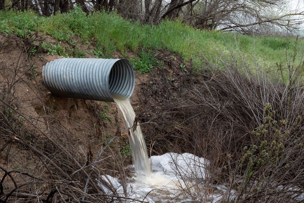
- Control flow energy at outlets. Concentrated discharge can erode slopes, ditch beds, and receiving channels. Outlet protection should suit expected velocities, soil erodibility, geometry, and environmental constraints.
- Design for inspection and maintenance. Inlets, manholes, ditch sections, culvert entrances, outlets, and cleanouts should be accessible for safe inspection and clearing.
- Preserve natural drainage where possible. Blocking or redirecting natural flows can shift flood, erosion, and instability risks elsewhere along the corridor or onto neighbouring land.
Details that commonly determine success or failure
Road-edge drainage deserves close attention. The pavement edge is structurally vulnerable because it has less confinement than the lane interior and can be exposed to shoulder infiltration. A shoulder drop-off, vegetation-covered outlet, or ditch too shallow to receive runoff can gradually weaken this area. Edge drains can work well in suitable conditions, but only if they are correctly graded, filtered, connected to dependable outlets, and maintained.
Culverts are another frequent source of failure. Their hydraulic capacity, entrance condition, alignment, cover, foundation support, and outlet protection all influence road reliability. Sediment, floating debris, or vegetation can block a culvert and force water across the road or into the embankment. Leakage at joints or along backfill may initiate internal erosion and settlement. At natural channel crossings, the design must also consider scour, debris behaviour, ecological flow needs, and the consequences of overtopping.
Construction quality matters just as much. Fine-material contamination of drainage aggregate, damaged geotextiles, poorly compacted trench backfill, crushed pipes, and undocumented changes to outlet elevations can undermine an otherwise sound design. Temporary construction drainage should keep water out of unfinished pavement layers and should not discharge sediment-laden runoff into permanent assets or downstream channels.
| Observed condition | Likely drainage-related mechanism | Useful investigation focus |
|---|---|---|
| Recurring edge cracking | Shoulder infiltration or weak, saturated edge support | Shoulder profile, ditch level, edge-drain continuity, moisture condition |
| Localized pavement depression | Leakage, internal erosion, or wet weak subgrade | Drainage crossings, pipe joints, ground voids, layer thickness |
| Water flowing over the carriageway | Blocked inlet, undersized route, or failed overflow path | Catchment changes, inlet condition, channel capacity, outfall level |
| Embankment slope erosion | Uncontrolled outlet discharge or concentrated runoff | Outlet velocity, erosion protection, slope drainage, downstream channel |
Maintenance is part of the drainage system
Drainage performance can decline gradually and go unnoticed because much of the system lies below ground or outside the traffic lanes. Inspection programmes should be timed around seasonal risks and major storms. Records should note standing water, sediment depth, blocked inlets, erosion, damaged headwalls, displaced protection, outlet submergence, vegetation obstruction, pavement-edge defects, and signs of seepage on slopes.
Condition data become more useful when considered alongside pavement and geotechnical observations. Repeated distress at the same chainage after heavy rainfall may justify targeted checks of moisture, layer condition, drain function, or groundwater response. Remote surveys can reveal broad drainage patterns, but field verification remains necessary where erosion, settlement, or slope movement could affect safety. Drainage also interacts directly with landslide and flood exposure, as discussed in Natural-Hazard Mitigation for Transport Infrastructure.
Using drainage evidence in renewal decisions
When a road requires rehabilitation, drainage should be assessed before the structural treatment is chosen. Relevant evidence may include ditch and culvert surveys, CCTV inspection of pipes where appropriate, outlet inspections, groundwater observations, falling-weight deflectometer results interpreted in light of moisture conditions, coring, trial pits, and laboratory testing of recovered materials. The aim is to distinguish surface ageing from a foundation-water problem.
A useful renewal record maps each defect against drainage features, terrain, recent rainfall, maintenance history, and observed moisture. Where distress clusters near blocked outlets or low points, drainage remediation may need to precede or accompany pavement work. If a permeable base has become contaminated with fines, clearing an outlet alone may not restore drainage. Where the subgrade has softened over a prolonged period, structural strengthening or reconstruction may be needed after the water source has been controlled.
At handover, the most valuable drainage records are often simple and specific: verified invert levels, pipe runs and connections, outlet locations, photographs taken before backfilling, material records for filters and drainage layers, access-point locations, and a maintenance map. They allow a future inspector to trace a wet pavement edge to its upstream collection point and downstream outlet instead of excavating without a clear basis.