A bridge’s visual form follows its load path. A shallow deck, sweeping arch, inclined hangers, or slender pylon each reveals how forces are collected and transferred through bearings and foundations into the ground. When that relationship is clear, the bridge looks convincing because its appearance reflects its structure. When visual gestures conceal inefficient force paths, complicate fabrication, or restrict inspection, they create long-term operational costs.
Good bridge architecture begins with engineering constraints, not with a form applied after the structural concept is settled. Span arrangement, navigation or roadway clearance, geotechnical conditions, hydraulic behaviour, construction access, exposure conditions, and inspection needs define the feasible options. Within those limits, proportion, rhythm, material texture, lighting, and the bridge’s relationship to its surroundings can create a distinctive civic structure without weakening reliability.
Function establishes the design envelope
The first decisions are usually governed by the crossing rather than a preferred bridge type. A bridge over a floodplain must avoid unacceptable effects on flow, scour, debris accumulation, and flood conveyance. An urban grade separation must accommodate clearances, utilities, railway interfaces, traffic staging, and limited pier locations. A valley crossing may be controlled by slope stability, foundation depth, erection access, and environmental restrictions.
These conditions help determine whether a short-span multi-pier bridge, continuous girder, arch, cable-supported system, truss, or another arrangement is appropriate. The comparison should address whole-life consequences, not simply the apparent efficiency of the superstructure. A long main span can reduce the number of supports in water or above traffic, but it may also require demanding erection methods, larger anchorages or foundations, specialist components, and more involved future inspection.
Key functional questions at concept stage
- What must be crossed? Define the physical corridor, required clearances, future widening allowances, operational restrictions, and construction windows.
- Where can loads safely enter the ground? Investigate bearing strata, settlement susceptibility, lateral ground response, liquefaction potential where relevant, slope behaviour, groundwater, and scour conditions.
- How will the bridge be built? Consider transport routes, crane positions, temporary works, launching or lifting operations, access beneath the deck, and the safety of adjacent road or rail operations.
- How will it age? Account for water management, de-icing salts, marine exposure, freeze-thaw cycles, fatigue, joint movement, replaceable elements, and inspection access.
- What hazards govern resilience? Assess seismic actions, wind, flood, collision, landslides, temperature movements, and site-specific environmental demands.
Aesthetics works best when it helps organize these answers. Pier placement that follows a coherent structural rhythm can reduce visual clutter while making the support system easier to understand. By contrast, visually minimizing a pier may be unsuitable if it shifts excessive demand to the foundations or requires a deck depth that conflicts with clearance requirements.
Structural proportion and visual coherence
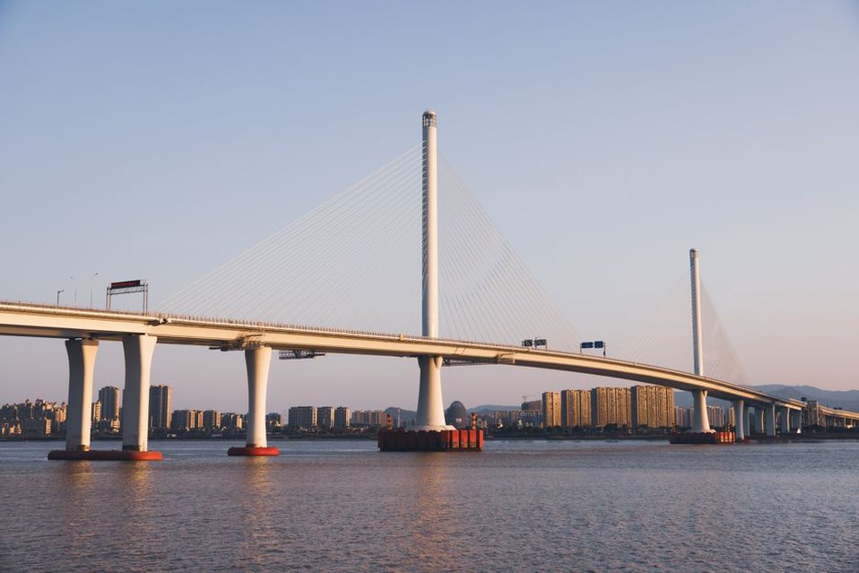
Bridges are perceived largely through silhouette, scale, repetition, and the relationship between deck and supports. Those qualities often arise directly from structural proportions: deck depth relative to span, pier width relative to height, support spacing, and the geometry of cables, arches, or truss members. The aim is not universal slenderness. A bridge that appears too thin for its setting can seem fragile, while an unnecessarily deep or heavily articulated structure may overwhelm a sensitive location.
Continuous systems often create a calm visual line because the deck passes uninterrupted over intermediate supports. Variable-depth girders can express higher bending demand near piers while allowing a shallower profile at midspan. Arches may suit sites where abutments can resist horizontal thrust and where the curved profile supports the required clearance and relationship to the surrounding terrain. Cable-stayed bridges can form a strong landmark, but their towers, stays, anchor zones, and vibration-control requirements should be justified by span, site constraints, and lifecycle capability.
Choose a coherent hierarchy
A bridge needs a clear hierarchy of elements. The primary load-carrying system—the deck, main girders, arch rib, tower, or truss—should remain visually dominant. Secondary elements such as diaphragms, parapets, lighting columns, maintenance walkways, drainage pipes, and utility supports should be coordinated so they do not become an accidental collection of competing lines.
This does not require hiding every functional component. Exposed bearings, cable anchorages, drainage outlets, or stiffening members can be appropriate when detailed with care. Consistency matters: repeated components need deliberate spacing, transitions at expansion joints should be resolved cleanly, and safety or maintenance additions should be anticipated in the original geometry.
| Design feature | Functional effect | Visual implication |
|---|---|---|
| Deck depth | Controls stiffness, structural capacity, utilities space, and clearance | Sets the apparent weight and horizontal line of the bridge |
| Pier spacing | Affects span demand, foundation count, hydraulic and construction constraints | Creates the rhythm perceived from approaches and beneath the deck |
| Parapets and barriers | Provide containment and user protection | Shape the deck edge and influence openness of views |
| Drainage arrangement | Limits leakage and water-related deterioration | Can preserve a clean soffit if integrated from the outset |
| Lighting supports | Serve operational safety and maintenance access | May clutter the skyline unless aligned with the structural grid |
Context is an engineering input, not decoration
Context is more than a scenic backdrop. It includes adjacent buildings, heritage features, road geometry, pedestrian routes, water levels, vegetation, noise requirements, and the scale at which people experience the structure. A motorway bridge viewed at speed needs a strong, simple form that reads at distance. A pedestrian bridge in a dense district is examined close up, where handrail detailing, deck texture, lighting glare, and the tactile quality of materials carry more weight.
Approach alignments matter as well. A skewed crossing can make a nominally regular support layout appear irregular, while a curved road deck introduces torsion that changes both load distribution and visual perspective. Aligning every visual feature orthogonally to the roadway may not suit a different principal crossing geometry. Physical or digital models, verified perspective views, and coordinated structural analysis can test relevant viewpoints, but renderings must never replace engineering checks.
At river crossings, piers and abutments form part of the channel system. Their shape, orientation, and placement influence local flow and debris behaviour, while foundation selection must account for scour and changing bed levels. An elegant arrangement with too many in-channel supports can create unnecessary hydraulic exposure and future maintenance demands.
Durability protects the intended appearance
Staining, leaking joints, corroded attachments, damaged coatings, and improvised utility installations can quickly erase the visual quality of a new bridge. Durability is therefore an architectural concern as much as a materials issue. Early detailing should establish how water leaves the deck, whether it can wet bearings or substructure surfaces, where debris may accumulate, and how vulnerable edges can be inspected and repaired.
A durable visual strategy does not depend on one material. Concrete can provide mass, continuity, and low routine maintenance when exposure conditions, cover, crack control, curing, drainage, and repair access are properly addressed. Steel can support efficient slender systems and expressive long spans, but coating systems, drainage, corrosion-prone interfaces, fatigue-sensitive details, and access must be planned for the full service period. Weathering steel may suit selected environments, but it requires careful assessment of wet-dry cycling, runoff staining, salt exposure, and protected zones where the intended patina may not form reliably.
Material junctions deserve particular attention. Dissimilar materials move differently under temperature change; sealants age; fasteners can corrode; and water may enter concealed interfaces. A visually minimal connection is not necessarily durable if it cannot drain, ventilate, be inspected, or be renewed. Guidance on bridge maintenance through drainage, inspection, and lifecycle planning is especially relevant when these details are developed.
Detailing decisions with high lifecycle value
- Provide positive drainage paths and avoid surfaces that retain water and debris.
- Keep drainage discharge away from bearings, expansion joints, piers, abutments, and traffic below.
- Make bearings, joints, cable anchorages, deck edges, and critical connections accessible for inspection and replacement.
- Coordinate conduits, utilities, and maintenance equipment before finalizing the visible form.
- Specify finishes and protection systems that can be safely inspected, cleaned, and renewed in the actual site environment.
Safety, movement, and resilience must remain visible in decisions
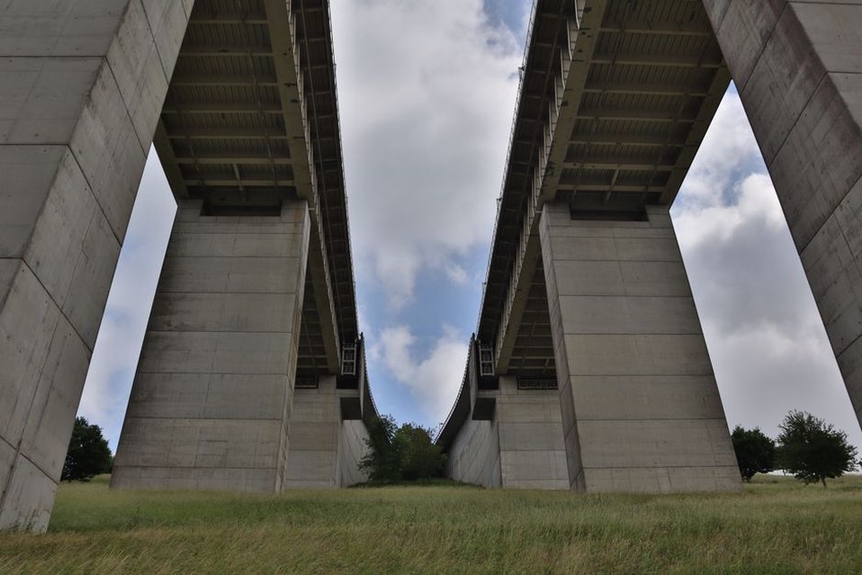
Bridge components move under temperature variation, traffic actions, concrete creep and shrinkage, settlement, and sometimes seismic excitation. Accommodating movement affects expansion joints, bearings, abutment details, utility crossings, barriers, and drainage. Attempts to conceal these interfaces can result in inaccessible or poorly drained arrangements. Movement zones should instead be treated as deliberate design elements with clear geometry and maintainable protective details.
Wind can govern temporary as well as permanent conditions, particularly for slender decks, tall piers, cable-supported structures, and erection stages. Aerodynamic behaviour, vibration of stay cables or parapets, pedestrian comfort, and construction-stage stability should be assessed in proportion to bridge type and exposure. The broader considerations are addressed in wind loads on transport infrastructure and their operational risk, including the distinction between structural response and service disruptions.
In seismic regions, architectural preferences must not interrupt a continuous, dependable load path from deck to foundation. Irregular stiffness, unequal pier heights, restrainer layouts, seat widths, unseating risk, and access for post-event inspection require project-specific analysis. A simple-looking bridge can still have complex seismic behaviour if its foundations rest on variable ground or its supports respond differently.
A collaborative concept process
Form and performance are best balanced when architects, structural engineers, geotechnical engineers, hydraulic specialists, construction planners, maintenance teams, and asset owners test options together before the preferred form becomes difficult to alter. Concept alternatives should be compared against clear criteria rather than selected solely through renderings or initial capital cost.
- Define mandatory constraints: route geometry, clearances, hazards, environmental limits, ground conditions, and construction restrictions.
- Develop several structurally credible typologies rather than cosmetic variations of a single preconceived scheme.
- Check load paths, preliminary member proportions, foundation implications, constructability, and serviceability for each alternative.
- Evaluate visual effects from approach, crossing, and under-bridge viewpoints, including day and night conditions where lighting is planned.
- Review inspection routes, replacement needs, drainage, access equipment, and likely deterioration mechanisms.
- Document why the selected form provides the best balance of safety, whole-life value, environmental fit, and architectural quality.
A useful final concept review centres on one practical drawing set: show the drainage route, inspection access, bearing or integral-support strategy, utility zone, expansion and movement interfaces, and likely replacement paths on the same elevations and sections used to assess appearance. If those elements cannot be accommodated without compromising the intended form, the concept has not yet reached a durable resolution.