A stronger column does not necessarily make a bridge safer in an earthquake. If a retrofit redirects demand to an unrestrained bearing, a short seat, or an older footing, the bridge may still lose its load path. Design therefore starts with the whole structure: how forces and displacements move through it, which components should resist movement, which should accommodate it, and what must remain repairable afterward.
Define the performance objective before choosing hardware
A bridge may need to remain usable after moderate shaking but only avoid collapse during a rare, severe event. The distinction matters. If emergency vehicles need immediate access, approach settlement, expansion joints, and bearing damage may matter as much as column strength. The objective must also separate shaking damage from permanent ground displacement: a bridge that tolerates cyclic motion may not tolerate a liquefaction-induced lateral spread.
Engineers establish a baseline using drawings, construction records, field measurements, material tests, and inspections for deterioration or previous repairs. Connections and foundations warrant particular scrutiny because the records may differ from what was built. The assessment should cover adjacent spans, bearings, seats, piers, abutments, foundations, and ground as one system. A discussion of soil–structure interaction in bridge foundations explains how foundation flexibility can change seismic demand rather than merely create a separate foundation problem.
Analysis should match the bridge and its hazards. Network screening can flag likely deficiencies; detailed nonlinear assessment may be warranted when yielding, pounding, isolation, or ground movement governs the outcome. Uncertainty in reinforcement details, bearing condition, or soil behavior belongs in the assessment, not behind a single precise-looking displacement result.
Keep the deck supported and connected
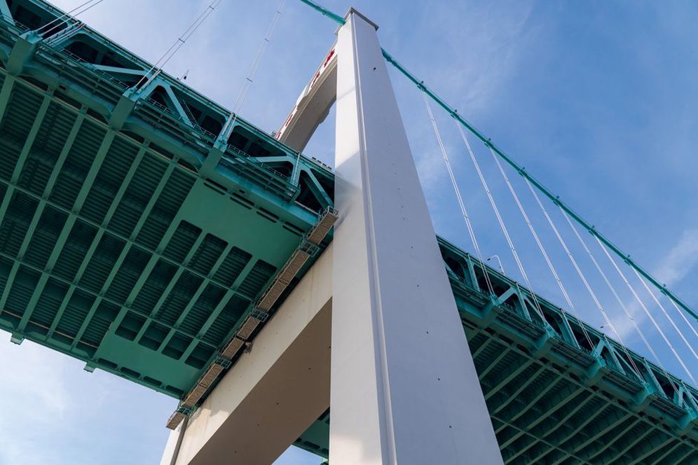
A pier can remain standing while its span moves beyond the available support. Restrainers, ties, and seat extensions address this unseating risk in different ways: a cable or rod restrainer limits relative displacement, while a seat extension increases landing length. Neither should be sized without checking expected movement, connection capacity, installation geometry, and the force it could transfer into existing concrete.
Shear keys can control transverse movement, but their intended behavior must be clear. A key that protects a bearing during frequent events may be expected to yield or fracture in stronger shaking. Making it stronger could instead raise demand on the cap beam or foundation. Bearing changes can likewise alter the force path across the bridge. Checks must cover temperature movement and normal service loads as well as seismic response; an earthquake restraint should not lock up ordinary expansion.
When bearings become part of the retrofit
Seismic isolation bearings lengthen the effective vibration period and can reduce forces transmitted through the bridge. They also permit larger movements at deck ends, which may affect joints, utilities, approach details, and clearances. Isolation is not a substitute for checking device properties, expected displacement, aging, maintenance access, and possible ground deformation. Supplemental dampers dissipate motion by a different mechanism, but their anchors and supporting members must still carry the device forces.
Improve columns without moving failure elsewhere
Older reinforced-concrete columns may lack the confinement reinforcement needed for stable cyclic deformation, particularly near potential plastic hinges. Steel jackets and fiber-reinforced polymer wraps can improve confinement and, when detailed for the deficiency, shear resistance. Results depend on the existing concrete, reinforcement arrangement, jacket termination, and continuity around the column. Better column behavior does not, by itself, fix a weak lap splice, cap-beam connection, or footing.
Concrete enlargement or added reinforcement may increase strength and stiffness, but added mass and changes in force distribution need to be assessed. Steel members pose other concerns: slender elements can buckle, and older connections may have limited deformation capacity. If a brace is strengthened or a connection replaced, engineers must check where forces go when that component no longer yields first.
- Confinement retrofits aim to make deformation in vulnerable column regions more dependable.
- Strengthening retrofits increase resistance but may also deliver greater seismic force to foundations.
- Restraint and support measures address loss of span support rather than column yielding.
- Isolation and damping change movement and force demand, with corresponding clearance and connection requirements.
Check foundations and ground displacement
Pier jackets and deck restraints cannot prevent failure if a footing slides, piles lose lateral support, or an abutment moves with liquefied soil. Options may include footing enlargement, added piles, stronger pile caps, or ground improvement. The appropriate approach depends on the failure mechanism as well as access, buried obstructions, water conditions, and construction beneath traffic. Ground improvement intended to reduce liquefaction triggering is not interchangeable with a structural measure intended to accommodate residual displacement.
Geotechnical investigation should distinguish cyclic shaking from slope movement, lateral spreading, and settlement. Where foundation records are incomplete, exploratory work can substantially change the scope. Ground models, predicted displacements, and structural deformation limits need compatible assumptions across the teams assessing them.
Design for construction and verify the result
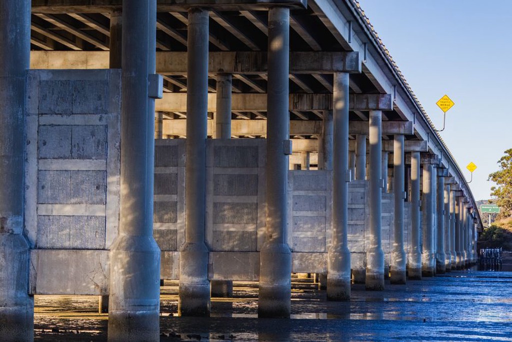
Retrofits are built around existing traffic and load paths. Temporary supports, bearing replacement sequences, drilling near reinforcement, and partial concrete removal can affect stability before the finished system is in place. Details also need to allow for inspection access, corrosion protection, drainage, fire exposure where relevant, and replacement of devices damaged in an earthquake.
Quality assurance should verify the details on which the chosen mechanism depends: anchor embedment and substrate condition, jacket fit and grout placement, bearing orientation, damper installation, and as-built deck-end clearances. Testing and inspection methods must suit the material and connection rather than rely on visual confirmation alone. Revised drawings should capture construction-stage discoveries, particularly hidden reinforcement or foundation dimensions that differ from the records.
After completion, the owner needs a baseline for future inspections. For an isolated bridge, that could include measured bearing positions and deck-end gaps at a recorded temperature. After an earthquake, those measurements provide a reference for judging whether a device returned toward its original position or has a residual offset that warrants closer examination.